Short Circuit in assembled design, why?

Thread Starter

gelliott

Joined Apr 19, 2019
13
Hi,
I've designed and prototyped a circuit I want to use for a project, but after I assembled it, I found a short between the power and ground. I'm not sure if it's because of the design, or because of the assembly. I suspect it's because of the assembly, since some of the parts I chose are maybe a bit too small or narrow-pitched for my skills with hand-soldering SMT. However, before I select new parts and redesign the PCB, I thought I should ask others to have a look at my schematic and tell me if anything is wrong with it that could cause issues.
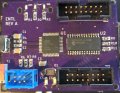
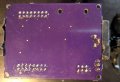
The design is based on an ATMega32u4 microcontroller, and includes MCP23017 I/O expander, micro USB, and some connector headers.

Using a multimeter, I found that there is a short between all VCC and ground pins. There is no short between the +5V coming from the 6-pin header to C3, and ground. I also used a multimeter to test an unassembled board and did not find any shorts, leading to my assumption that the short was introduced during assembly. However, I'm not sure if there's something with the design that could lead to a short by correctly placing and soldering the components.

My current guess is that the micro USB component is too small for me to hand-solder properly. The pins are fine-pitched, and underneath the component, and it's possible that there's a bridge somewhere under there, but I can't tell. But VCC doesn't go to that part so I'm not so sure that's the source of the short.

I've attached a PDF of the schematic, pcb, and photo of it assembled. I've also documented some of the design online, which includes larger pictures here: https://grantelliott.ca/2019/03/20/button-controller.html

Much thanks for your time
 

Attachments

Ya’akov

Joined Jan 27, 2019
10,240
Unfortunately, your PCB photo suffers from motion blur to the extent the pins on U1 and U2 appear to be bridged in various places.

Can you take a sharper image of the board?
 

djsfantasi

Joined Apr 11, 2010
9,237
Unfortunately, your PCB photo suffers from motion blur to the extent the pins on U1 and U2 appear to be bridged in various places.

Can you take a sharper image of the board?
Plus, a clear picture of the other side of the PCB may be instructive.
 

Thread Starter

gelliott

Joined Apr 19, 2019
13
Here is a (hopefully) better picture of the top. There's not much going on at the back, but I've attached a picture just in case.
I had a good look at the solder joints on the ICs and couldn't see any bridging, but my amateur eyes may be missing something.
 

Attachments

narkeleptk

Joined Mar 11, 2019
586
I think its probably in your soldering. Wick a bit of it up. Add flux and use hot air to re-flow it.


If you think its the micro usb, remove it and see if the short is gone. They are indeed a pain to hand solder.
 

AnalogKid

Joined Aug 1, 2013
12,142
If it is a dead short (not something like 3 ohms), track down and inspect the soldering at every Vcc and GND pin. You must be able to see a clear gap around all four sides of each land.

ak

A side note, some professional advice about your schematic. Not bad for a first try, one gold star for having reference designators. But -
All Grounds point *down*.
All positive power sources point *up*.
Never overlap traces and text, component outlines, etc.
Never overlap text.
In fact, never overlap anything.
No matter what the component orientation is, all text should be upright.
Add a title block with the project name, file name, and date. You'll thank me later.
All of this will make the schematic larger. So what? Electrons are cheap.
 

Thread Starter

gelliott

Joined Apr 19, 2019
13
I think its probably in your soldering. Wick a bit of it up. Add flux and use hot air to re-flow it.


If you think its the micro usb, remove it and see if the short is gone. They are indeed a pain to hand solder.
I don't have a rework station yet, but now seems like a pretty good time to get one. I'll see what I can do with an iron and some wick in the meantime.

Are pins 15 and 16 (?) on U2 bridged?
I don't think so, but they very well could be. There's a bit of extra flux in the picture that makes it hard to tell. For some reason, the camera really likes picking that stuff up. I'll try cleaning it up a bit more and see if that helps. They're all meant to be connected to ground anyways.

If it is a dead short (not something like 3 ohms), track down and inspect the soldering at every Vcc and GND pin. You must be able to see a clear gap around all four sides of each land.
How would I be able to tell the difference? So far I've been using the continuity mode on my multimeter. Either way, it seems like another pass at cleaning up the solder joints on the pins is in order.

A side note, some professional advice about your schematic. Not bad for a first try, one gold star for having reference designators. But -
All Grounds point *down*.
All positive power sources point *up*.
Never overlap traces and text, component outlines, etc.
Never overlap text.
In fact, never overlap anything.
No matter what the component orientation is, all text should be upright.
Add a title block with the project name, file name, and date. You'll thank me later.
All of this will make the schematic larger. So what? Electrons are cheap.
Thank you for your advice! Some of that text is pretty impossible to read, especially when it's exported. I'll tidy things up
 

narkeleptk

Joined Mar 11, 2019
586
You may could try solder paste on pads and using the hot air to put it on. If no solder paste you could tin each pad a little, add flux to micro plug and then use hot air to put it on. I would heat pcb a bit before placing the usb plug. You can't hot air the plug too long because it has a bit of plastic inside that likes to melt pretty quickly.
 

sghioto

Joined Dec 31, 2017
8,634
There is no short between the +5V coming from the 6-pin header to C3, and ground.
On the schematic and on the PCB design you have C3 (10uf ) in series with all the Vcc supply pins on the micro to 5 volts. How is that suppose to work?
SG
 
Last edited:

Thread Starter

gelliott

Joined Apr 19, 2019
13
On the schematic and on the PCB design you have C3 (10uf ) in series with all the Vcc supply pins on the micro. How is that suppose to work?
SG
That's a rather timely question, because after re-assembling everything and verifying there's no shorts, I'm having issues programming the chip. The voltage to the Vcc pins were nowhere close to 5V. It's entirely likely I misunderstood the block diagram from the datasheet for powering the chip, as well as the schematics for other minimal circuits for the MCU.
What should the schematic for the decoupling cap look like between the 5V supply at the ISP pin 2 and the VCC pins?
 

SLK001

Joined Nov 29, 2011
1,549
Nevermind, I just looked it up and see my mistake...oops!! Well, at least this was good practice in assembling.
It's a shame that your first attempt was a failure. What PCB design package did you use? Is there a DRC (Design Rules Check) in it? Did you use it? Did you even manually look over your design? Have another person look at it? If you've got fairly thick skin, you could submit it to the forum here to have everyone nit-pick it to death! Who knows, you might even get some good advice for your design!

You'd be surprised at what running a DRC can show you about your design.
 

Thread Starter

gelliott

Joined Apr 19, 2019
13
It's a shame that your first attempt was a failure. What PCB design package did you use? Is there a DRC (Design Rules Check) in it? Did you use it? Did you even manually look over your design? Have another person look at it? If you've got fairly thick skin, you could submit it to the forum here to have everyone nit-pick it to death! Who knows, you might even get some good advice for your design!

You'd be surprised at what running a DRC can show you about your design.
It's fine, I figure I'll have a few bumps along the way as I learn. What's a few more bucks for another run when I figure out what went wrong with this attempt, right? I used Eagle, with the OSHPark extension. I did DRC and ERC, and obviously looked over my design :) Just not with an experienced eye. I'm open to whatever useful feedback can be offered, but I didn't want to be yet another person asking all kinds of dumb questions and would rather just try it for myself and go from there.
 

nsaspook

Joined Aug 27, 2009
16,330
It's fine, I figure I'll have a few bumps along the way as I learn. What's a few more bucks for another run when I figure out what went wrong with this attempt, right? I used Eagle, with the OSHPark extension. I did DRC and ERC, and obviously looked over my design :) Just not with an experienced eye. I'm open to whatever useful feedback can be offered, but I didn't want to be yet another person asking all kinds of dumb questions and would rather just try it for myself and go from there.
We all make sometimes dumb mistakes even if you've been building things for decades.
I've used OSHPark for several boards. How do you like their service?
 

Thread Starter

gelliott

Joined Apr 19, 2019
13
We all make sometimes dumb mistakes even if you've been building things for decades.
I've used OSHPark for several boards. How do you like their service?
They seem good to me, maybe a bit slow, but I understand they get them done in China and so the shipping can take a while. But it's painless sending a design to them from Eagle, they managed to drill/cut the oval "holes" I added by my LEDs which was nice, the pads and through-holes are well-done, and everything is done exactly how it was designed. The price seems great too. I don't have any experience with other manufacturers to compare them to though. I've been eyeing up JLPCB for another run though.
 
Top