Facebook
 Google
 GitHub
 Linkedin
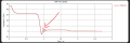
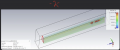
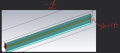
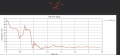
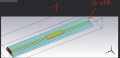
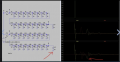
Hello , As you can see in the simulation when we have a short load we have 0 impedance in the end because its 0 ohms.
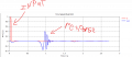
On the other hand as you can see below in the simulation when we have inductive load then we have negative bump in the tdr.
A shorting via can ve viewed as inductor because its a straight line .
Why in our EM simulation I dont have negative bump as in the LTspice simulation?
Thanks.

On the other hand as you can see below in the simulation when we have inductive load then we have negative bump in the tdr.
A shorting via can ve viewed as inductor because its a straight line .
Why in our EM simulation I dont have negative bump as in the LTspice simulation?
Thanks.
Attachments
-
 439.5 KB Views: 7
 -
 603.3 KB Views: 9
 -
 754.5 KB Views: 9