Relay contacts welding - inductive motor load - RC snubber question

Thread Starter

peugot

Joined Sep 15, 2025
9
Hi all,

Situation
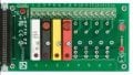
I have a PCB with 2x relays to control a motor (0.6A, 135W). The relays are used in a way that it can rotate the motor forwards and backwards. The relays are wired in a way that even if you enable them both, the 'forward' direction will overrule the 'backwards' direction. So only 1 direction is active at a time. The neutral wire is always connected, the live wire is the one that gets switched for forward or backward movement.

Now the relays seem to be welding together after some time. I noticed quite some sparks when I turn the relays off. All other components and the parts on the PCB continue to work just fine, it's only the relay itself. Since I have an inductive motor load, a (huge) voltage spike is created when switching the relay off, which causes arcs over the relay contacts.

RC Snubber specs
For this I've added a general RC snubber: 1757944124228.png
with the specs:
Resistor: 220 Ohm
Capacitor:
  • CBB22 104J630V
  • 0.1uF
  • 630V
  • 5% tolerantie
Varistor:
  • AC voltage: 300V
    Rated DC voltage: 385V
    Maximum terminal voltage Vc: 775V
    Varistor type: Metal oxide varistor
    Peak surge current @ 8/20µs: 2.5kA

Tests
I've tried different ways of connecting the snubbers:
1. Parallel to the motor load
2. Parallel to the switch contacts relay

For both these methods the arcing is still there! It doesn't really seem to do make a difference..

Question
Does anyone maybe have tips for me what is best suited for my use-case? Am I doing something wrong here? Or maybe tips to point me into the right direction? Thanks in advance!
 
Can you confirm the snubber resistor value. 220 ohms is not good for anything, it should be much lower value.
These low cost boards always seem to have the same parts:
MOV 10D471 (470V 1mA), Cap CBB22 0.1uF 630V, Res 3W Metal Film 220 ohms? ±1% Red-Red-Blk-Blk-Brn

Another trap is that the relays do take time to switch. Depending on their size 10-25msec I've measured to release.
Any overlap happening where they are both pulled-in can be another source of arcing. You might be switching them poorly, especially if going FWD-REV-FWD etc. a lot.
 

Thread Starter

peugot

Joined Sep 15, 2025
9
@sghioto: It's an AC motor, 230V.

@MaxHeadRoom: part no is 2961150 from Phoenix.

@prairiemystic: yes I can confirm the resistor value is 220 ohms. When switching it always goes to a 'motionless' state before switching it forwards or backwards again. Which value for the resistor do you recommend? (Can I then leave the capacitor value unchanged?)
 

Thread Starter

peugot

Joined Sep 15, 2025
9
@MaxHeadRoom, thanks for the reply!

1. Hmh, but the specifications should be suited for my use-case right?

2. Could you recommend/suggest any other relay with this (rather small) form factor? I chose this because of size constraints, and this relay was pretty small and within specs.

3. Still, even tested with a bigger and stronger relay, there are big sparks. A big relay does not seem to break down, but best practise is to use a snubber I'd assume? Just wondering why my snubber doesn't seem to stop the arcing on both these relays..
 

panic mode

Joined Oct 10, 2011
4,926
relays carry their highest ratings - in this case 6A. but... reality is that often they have to be derated, specially when load is not purely resistive or if not AC. just check the specs, AC specs show that at 230VAC this is still ok for up to 3A. that is 50% derating which is not bad for inductive load. but even at AC, N/O contact is rated higher than N/C contact. also note that the same "6A contact" is suddenly only good for 0.1 or 0.2A at rather low voltages if you switch to DC.

so 3A should suffice? maybe... i think the 3A rating is rather generous. personally i would not expect those miniature relays used for anything but signals.

it says that for motor load N/O contact of that signal relay is rated for 1/4 HP (746/4 = 186.5W). and since voltage is 240-277VAC, maximum current at 240VAC is 0.777A.

shaded pole motors have very poor power factor (50% or lower). single phase motor with starting capacitor have power factor of some 10-20%. so if your load has real current of 0.8A, apparent current is some 6-8A. that is way beyond ratings of the little relay.
using snubber can improve results but life of this small relay would still be very short.
for powering loads, use some small power relay like Wago 788-353.
 
Last edited:
For the snubber resistor, I start with 33-47 ohms and something that can take a small 250V spike as the cap charges/discharges. That looks like 1W up to 3W but if you have smaller wattage you can just try it a few times. I would try lower value resistors and see if the arcing is reduced. This would tell you if the snubber is working well. As I mentioned I think 220 ohms won't do much, it was probably 22 ohms until the entire country got it wrong lol.

It depends on the motor, how nasty the back EMF is. Mechanical backspin, a run capacitor, residual magnetism etc. can store a lot of energy. When you pull power to an electric motor this stored energy can eat up and damage contactors.

My last point is make sure the relays do not overlap: crowbar mains during switching. Have to see a schematic of what you've got.
 

schmitt trigger

Joined Jul 12, 2010
2,055
My last point is make sure the relays do not overlap: crowbar mains during switching. Have to see a schematic of what you've got.
This is *very important* as relays usually close faster than opening.
Not only for mechanical reasons, but the current flowing through the freewheeling diode causes the magnetic field to continue for a few milliseconds after it is de-energized.
But without actually seeing your schematic and how the relays are being driven, this could only be ignorant speculation.
So I join the chorus, please show us your complete circuit.
 

Thread Starter

peugot

Joined Sep 15, 2025
9
Thanks for all the replies again!

@MaxHeadRoom I can't find this, it only mentions the few specifications I've already given, seems like a very general motor. If it helps, it's a general motor for sun blinds, 230V AC, 0.6A, 50Hz.

@panic mode with a smart energy meter I measure 0.6A, so the apparant current could be way higher then. Thanks for the suggested Wago 788-353, I can't really use this one though, because the relays must be placed on a PCB, and it's a little size constrained as well. Hence the reason these small relays are chosen in the first place.

@prairiemystic I've tested down to ~2.5-3 ohms and only then it seems to work great! Not sure if this is a practical/safe value to use. I've put this both in parallel to the motor, or in parallel to the relay contacts, both work. I notice that even though I connect the RC snubber in parallel to only the UP relay, it also stops sparking for the DOWN relay! So L-S1-S2, I connected in parallel to L-S1, but it also prevents sparks on L-S2. I believe this is because of the way the relays are hardwired, in the off state (when sparking happens) relay 1 and relay 2 effectively have a connection on their top pins, so the RC snubber is basically already in parallel to both realys, see schematic below.

@schmitt trigger see below. The relays are wired in such a way that both relays can never be on at the same time. The UP relay will always overrule the DOWN relay.
1758182017328.png
 

Ian0

Joined Aug 7, 2020
13,112
I see a flaw in the design . . .If RL2 is ON and the motor is running down, and RL1 is switched in, the motor immediately switches from down to up without a pause chance to stop. That's going to cause some arcing.
 

Thread Starter

peugot

Joined Sep 15, 2025
9
Ian0: that's on purpose. In reality this doesn't happen though, software prevents that. It's just a last safety measure in the hardware so that both motors can never be on at the same time.
 

Thread Starter

peugot

Joined Sep 15, 2025
9
Would this relay be better suited? ALQ6F12S. It mentions 1/2HP 250V AC (so ~375W), and inrush 10A 250V AC (cos pf = 0.4). Furthermore contact rating of 5A 250V AC. Motor load inrush 30A peak/0.5s with steady 3A rms cos pf = 0.5 250V AC.

There are so many specifications to look at, sometimes I'm a bit lost and confused at which ones are really the crucial ones.
 

MaxHeadRoom

Joined Jul 18, 2013
30,590
If you do end up with using a sealed relay, I would drill a small hole in one corner of the top, (they often have a small dimple for hole posn.).
This reduces ionization of the air trapped inside.
 

ChuckMcM

Joined May 20, 2024
3
What you want is a zero crossing detector. Basically put a gate on the signal to change the relay that waits until the AC line is at 0 volts (or close to zero) before it tells the relay to switch. That will will introduce a small delay (depending on your line frequency) into the switching but will avoid the inductive arc kickback you are seeing.

Even if they don't weld themselves together, the arcs will carbonize the contacts which will develop progressively more resistance and at some point you might have a "thermal event".
 

MisterBill2

Joined Jan 23, 2018
27,294
What I do not recall seeing is the actual current ratings of the relays that are welding contacts. Or even the relay voltage rating. A relay with ONE AMP and 200 volt contacts will not last long in that application. AND no snubber is likely to extend the life very much. The starting inrush is not what a snubber will protect against.
 
Last edited:

Thread Starter

peugot

Joined Sep 15, 2025
9
Alright thanks again, so does that make the relay I sent suited?

I'll also look into the zero cross voltage detection, I just read some comments online that due to the bouncing contacts you will still get arcing, because you may switch it off at 0-volt, but when it bounces there is voltage on it again. I think I will follow this circuit with the optocoupler: https://circuitdigest.com/electronic-circuits/zero-crossing-detector-circuit-diagram
 
Top