wanted short circuit Protection for LM338(TO-3)

Thread Starter

ommsiva

Joined Mar 13, 2024
52
Hi all,

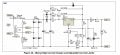
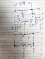
I need Short Circuit Protection for LM338.

I have 20V @ 5Ampere transformer after rectification with FWR and Capacitive Filter(4700uF,63V), the rectified output was 28V.
Two times while testing the LM338 went to break down due to unintentional short.

Kindly Suggest me short circuit protection circuit.

1756647210967.png
 

Thread Starter

ommsiva

Joined Mar 13, 2024
52
fuse ?
you should also have a reverse diode across the ldo,
also that 4.7 mF capacitor , is that on the input or the output of the ldo ?
check data sheet for capability of the ldo.
https://www.ti.com/lit/pdf/sszt658
Dear Sir,

1)On the output i had 5Amp Fuse , it never went to break down instead LM338K
2) 4700uF input filter Cap
3) its not a LDO, It need head room of minimum 3V.

Since 5 amp current is involved , what should the protection circuit needed?
 

drjohsmith

Joined Dec 13, 2021
1,549
Dear Sir,

1)On the output i had 5Amp Fuse , it never went to break down instead LM338K
2) 4700uF input filter Cap
3) its not a LDO, It need head room of minimum 3V.

Since 5 amp current is involved , what should the protection circuit needed?
whats your Vout ?
 

drjohsmith

Joined Dec 13, 2021
1,549
Sir,

Vout was 5V.

I can understand(28-5)*5=23*5=115W, Exceeding power dissipation capability.

we have to protect, suggest some methods.
the power dissipation is inherent,
you need to get rid of that heat, or re think your design.

you looked at those links I posted very quickly
 

schmitt trigger

Joined Jul 12, 2010
2,027
If your transformer has a center tap, use a full wave center tap configuration and your head voltage will drop in half, also halving the power dissipation. Of course, I have a gut feeling that you are going to tell us that a center tap is not available.
Then your other option would be to employ an adjustable SMPS pre-regulator and adjust its output voltage to 8 volts. But I also have a feeling that for some reason you are also going to reject that solution.
Then you require to add a BIG power resistor in series with the regulator input to dissipate all that extra power. But again you are going to come back and tell us that those resistors are too large and too expensive. That you want a half-dollar solution no larger than a square inch.
 

Thread Starter

ommsiva

Joined Mar 13, 2024
52
If your transformer has a center tap, use a full wave center tap configuration and your head voltage will drop in half, also halving the power dissipation. Of course, I have a gut feeling that you are going to tell us that a center tap is not available.
Then your other option would be to employ an adjustable SMPS pre-regulator and adjust its output voltage to 8 volts. But I also have a feeling that for some reason you are also going to reject that solution.
Then you require to add a BIG power resistor in series with the regulator input to dissipate all that extra power. But again you are going to come back and tell us that those resistors are too large and too expensive. That you want a half-dollar solution no larger than a square inch.
Dear sir,

Whether this short circuit protection will work, if we replace LM317 with LM 338k( avoid current boosting transistors as it was started initially with lm338 and two resistor for setting output voltage)?
 

Attachments

Last edited:

drjohsmith

Joined Dec 13, 2021
1,549
Dear sir,

Whether this short circuit protection will work, if we replace LM317 with LM 338k( avoid current boosting transistors as it was started initially with lm338 and two resistor for setting output voltage)?
Can you provide the reference to where that circuit is from please .
It looks like it's designed to charge batteries , hence why it has relay to isolate the battery when there is no power going into the ldo circuit.
It also has temperature cutout , I guess to stop battery from being charged when it's too cold. .

Can I suggest , instead of almost random selection of sort of circuits being presented , you state what are your requirements .

The forum has a huge selection of very talented engineers for you to dip into .
 

Thread Starter

ommsiva

Joined Mar 13, 2024
52
Can you provide the reference to where that circuit is from please .
It looks like it's designed to charge batteries , hence why it has relay to isolate the battery when there is no power going into the ldo circuit.
It also has temperature cutout , I guess to stop battery from being charged when it's too cold. .

Can I suggest , instead of almost random selection of sort of circuits being presented , you state what are your requirements .

The forum has a huge selection of very talented engineers for you to dip into .
Dear sir,

Circuit Taken from
https://sound-au.com/project196.htm


Need to construct ps variable from 1.2 to 24V at 5 ampere using Lm338. Two times the regulator went to breakdown, need protection circuit when short circuit happens at the output.
 

drjohsmith

Joined Dec 13, 2021
1,549
Dear sir,

Circuit Taken from
https://sound-au.com/project196.htm


Need to construct ps variable from 1.2 to 24V at 5 ampere using Lm338. Two times the regulator went to breakdown, need protection circuit when short circuit happens at the output.
Ta for that .

Requirement questions

Vin ? AC or DC in ?
Do you need to use a lm388, if so why ? Who's setting that requirement ?
Vout is 1v2 to 24v at 5 Amps
What do you want the output to do if you try to take more than 5A ? Turn off, lower voltage to keep a constant current of 5A ?
If it's to turn off in over current , how is it to be turned on again ?

To use a linear regulator like a ldo , you would be looking at around 2V greater input than max output. Say 28V

At your minimum out of 1v2 , and 5 A
Your linear regulator is going to have to dissiate ( 28-1.2) * 5 = 134 watts of heat whilst keeping the ldo / transistors below around 70 degrees. That's around a 0.3 degree per watt heat sink you need. Do you have room for that ?
 

drjohsmith

Joined Dec 13, 2021
1,549
I've just checked the lm338 data sheet .
"6.4.4 Operation in Self Protection When an overload occurs
, the device shuts down Darlington NPN output stage or reduces the output current to prevent device damage. The device automatically resets from the overload. The output may be reduced or alternate between on and off until the overload is removed"

why do you think short circuit has killed the device ?
have you included the protection diodes as described in the data sheet ?
 

Thread Starter

ommsiva

Joined Mar 13, 2024
52
I've just checked the lm338 data sheet .
"6.4.4 Operation in Self Protection When an overload occurs
, the device shuts down Darlington NPN output stage or reduces the output current to prevent device damage. The device automatically resets from the overload. The output may be reduced or alternate between on and off until the overload is removed"

why do you think short circuit has killed the device ?
have you included the protection diodes as described in the data sheet ?
Sir,

I have provided protection diode.

Whether this high current battery charging circuit idea ,where a current sense resistor and npn transistor help in limiting the current?
 

Attachments

drjohsmith

Joined Dec 13, 2021
1,549
Sir,

I have provided protection diode.

Whether this high current battery charging circuit idea ,where a current sense resistor and npn transistor help in limiting the current?
There are two diodes needed for reveres protection ,
Did you use two and of what type ?

Why do you think over current killed the ldo when they have protection built in

Can you share picture of your current design please

Your now saying to use lm317 , I thought u said your requirement was to use the lm388

Please answer all the questions we've asked , then we can get back to you.

Just randomly changing the requirement and suggesting circuits is not designing or engineering
This is not software , you can't just mix and match .
 

Thread Starter

ommsiva

Joined Mar 13, 2024
52
There are two diodes needed for reveres protection ,
Did you use two and of what type ?

Why do you think over current killed the ldo when they have protection built in

Can you share picture of your current design please

Your now saying to use lm317 , I thought u said your requirement was to use the lm388

Please answer all the questions we've asked , then we can get back to you.

Just randomly changing the requirement and suggesting circuits is not designing or engineering
This is not software , you can't just mix and match .
Sir,

Attached the circuit, the diode were 1N4007 .
 

Attachments

drjohsmith

Joined Dec 13, 2021
1,549
Sir,

Attached the circuit, the diode were 1N4007 .
Thanks.
Your output diode is in the wrong place,
Can you answer the other questions please ?
In addition .
What output voltage and current were you measuring before the last two broke ?
What were you doing at the time ?
What load was the PSU connected to ?
 

Thread Starter

ommsiva

Joined Mar 13, 2024
52
Thanks. Can you answer the other questions ?
In addition .
What output voltage and current were you measuring before the last two broke ?
What were you doing at the time ?
What load was the PSU connected to ?
Sir ,

One time it was 12v set with output setting resistor. Unfortunately it was shorted because I soldered small wires and tested.


Other time it was Literally a short at the output , although regulator was connected in heatsink for both the cases.


Thank you sir
 

drjohsmith

Joined Dec 13, 2021
1,549
Sir ,

One time it was 12v set with output setting resistor. Unfortunately it was shorted because I soldered small wires and tested.


Other time it was Literally a short at the output , although regulator was connected in heatsink for both the cases.


Thank you sir
Thank you
And the other questions please
 
Top