Sensor not working when connected to relay

Thread Starter

perky416

Joined May 5, 2017
16
Hi guys.
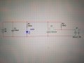
I am using a laser sensor that outputs 5v when it detects the light of the laser. I am trying to use the output to energise a relay.

The relay was originally a part of a pcb where you could move a jumper to select whether to energise the relay with a high or low signal, power led, energised led etc.

The sensor circuit works perfect on its own, it outputs 5v no problem, however when connected it to the ini of the relay pcb the sensor would only output 1.4v and therefore would not energise the relay. When adding a direct 5v supply to the ini of the relay circuit it energised fine. I decided to de-solder the relay to use it on its own. Again when not connected the sensor circuit outputs 5v no problem, however when connected to the relay it now reads 0v. The relay energises ok when i put a direct 5v source so the relay is working fine.

Does anybody have any idea what could be happening?
I have attached a circuit diagram of how it currently stands with the sensor circuit wired direct to the relay.

Thanks
 

Attachments

bertus

Joined Apr 5, 2008
22,270
Hello,

Do you have the specifications of your laser detector?
It can well be that the detector can not drive the relays directly.

Bertus
 

Thread Starter

perky416

Joined May 5, 2017
16
Hi bertus,

It is just a cheap sensor i purchased on amazon. I have attached a picture. The pcb labels is as DS18B20 however i havent been able to find anything about it on google all i get is a themal sensor of the same name.

Regards
 

Attachments

Thread Starter

perky416

Joined May 5, 2017
16
This is the link to the actual item i purchased:
https://www.amazon.co.uk/gp/aw/d/B07CXZYDVS?psc=1&ref=ppx_pop_mob_b_asin_image

There are examples of this being used on youtube.

Also another seller on amazon advertises the same sensor driving a relay, the relay pcb is different to the one i have however the actual relay looks to be the same. I have attached a picture from their listing.

Thanks
 

Attachments

Wolframore

Joined Jan 21, 2019
2,609
Sensors generally do not have enough current to drive a relay. They are meant to be used to detect something and output a voltage that can be used to trigger something else.

it’s a phototransistor capable of sinking about 20mA max.

all it does is output high when laser is detected you may be able to switch a mosfet with it then drive a relay. The example above works because there’s an onboard transistor.

https://www.codrey.com/electronic-circuits/the-mysterious-laser-receiver-sensor-module/
 

SamR

Joined Mar 19, 2019
5,031
That is exactly what is happening. It needs more current to power the relay and is driving the Voltage down trying to do so.
 

Wolframore

Joined Jan 21, 2019
2,609
Please upload your wiring diagram and or picture of your setup. I believe that module has onboard transistor/opto... although the way they didn’t that circuit you wonder why they even bothered with opto... it’s not really isolated
 

Wolframore

Joined Jan 21, 2019
2,609
Hey wolframore, thanks for the link, some useful info there.
This is a link to the relay pcb i purchased, according to the description the trigger current is 5ma:

https://www.amazon.co.uk/gp/aw/d/B07QM1P61V?psc=1&ref=ppx_pop_mob_b_asin_image

Even with this it didnt work as mentioned the output was 1.4v
output of 1.4v is not high enough to register as logic high.

it sounds like a MOSFET in between would fix your problem. A mosfet is a voltage controlled device and would not require any significant current and would act as a buffer between the module and relay. It doesn’t matter since you can change the jumper so I would use N channel.
 
Last edited:

Tonyr1084

Joined Sep 24, 2015
7,852
output of 1.4v is not high enough to register as logic high.

it sounds like a MOSFET in between would fix your problem. A mosfet is a voltage controlled device and would not require any significant current and would act as a buffer between the module and relay. It doesn’t matter since you can change the jumper so I would use N channel.
Agreed.

One thing to be certain of - the output of the laser sensor goes high and turns something on - anything - doesn't matter. Using a MOSFET will work great with that "High" signal. But without a corresponding "Low" signal, the FET can stay on long after you want it to shut off. I don't know if the output of your sensor goes High and Low or just High and Open. If the latter, you'll need a pull-down resistor to shut the FET off.
 

Tonyr1084

Joined Sep 24, 2015
7,852
You always need a pull down with a mosfet. You can’t rely on a signal to be correct especially at startup.
While I agree that a pull-down is necessary, it's not always the case. IF (big "IF") the sensor output has a hard HIGH and a hard LOW then you can depend on the sensor to shut off the MOSFET. Only if the output is a hard HIGH and OPEN (not a low) then yes, a pull-down is necessary.
 

Wolframore

Joined Jan 21, 2019
2,609
@TonyR I understand what you’re saying and if you don’t mind something that turns itself on at power up you can get away with it... do you understand what I’m saying? This is the reason why CMOS inputs can’t be left floating. the output is undetermined even if for a brief moment. Im working on a project in which this would be dangerous. If your sensor provides the pull down then it’s already there but it’s necessary in most situation.
 

Tonyr1084

Joined Sep 24, 2015
7,852
@Wolframore Yes, I understand that.

In the TS question, I'm under the impression something is off until he turns it on. Being turned on by a momentary push button. To me that suggests there's always power available, meaning the laser sensor is "Ready" but not active. In such a case I would expect (perhaps foolishly - go ahead and point that out - I can take criticism) I would expect the sensor output to be low. Again, this is with the assumption the sensor output is both HIGH and LOW. A pull-down resistor will add some security to the system if one is so concerned. I'm not saying you don't need it - just saying that in the case of an operating circuit, High and Low are both presented as an absolute condition.
 

Wolframore

Joined Jan 21, 2019
2,609
I was mistaken about the output from the sensor. I just took another look at the schematic it’s designed to output a low when light is detected. It has a pull-up built in for proper operation. 5v output in the dark, in the TS’s case 1.4v when there is light, the jumper on the relay should be set to L position.

don’t try to switch on H setting the pull-up only gives you 500 uA... no mosfet needed just change jumper.

@Tonyr1084 ensuring proper off conditions is one of the rules for using mosfets. There are a number of great things written on the subject.. it can be annoying to dangerous and unreliable at best without it.
 
Last edited:

Tonyr1084

Joined Sep 24, 2015
7,852
@Wolframore OK.

Yeah, the circuit does have a 10KΩ pull-up. Ignoring the relay coil resistance, 10,000Ω at 5 volts is going to be 500 µA (micro-amps). There's NO WAY that can pull in a relay coil. Add in the coil resistance and you get even less amperage. A driver circuit is definitely needed.
 

Tonyr1084

Joined Sep 24, 2015
7,852
@perky416 the reason why you're seeing such a low voltage is because the 10KΩ resistor and the coil resistance forms a voltage divider. With math I get weak in the knees, but you should be able to calculate the coil resistance just knowing the voltage across it along with the amperage. I'll try - but I'm probably wrong: 1.4 ÷ 0.0005 = 2800Ω. That doesn't seem like a reasonable answer. That's why I say I'm probably wrong. I KNOW I'm only using the current calculation for just the 10KΩ resistor, but that was because I've assumed the coil resistance to be VERY low. Maybe a few hundred ohms. If I add in the 2800Ω coil resistance (calculated) then the current drops to 391 µA (0.000391 amps). But I'm sure my numbers are off.
 
Top