Facebook
 Google
 GitHub
 Linkedin
Hello everyone,
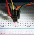
I have this new LM35 temperature sensor 10pcs. This is my very first encounter with this specific component so I don't know what readings to expect from it. I manage to find this component in the Proteus list of components and in simulation, it showed a linear or equivalent increase in output voltage with LM35 temperature. More specific, 10mV per 1°C.

In reality, I'm not getting this result at all. I'm getting 0V reading.
I start to think my components are bad?
But I also manage to make them work !!! at least to collect a more correct voltage from it's output, Im not sure how correct is the temperature reading converted in mV, but is very close to what direction of working the simulator showed me it should be like.

So if the opamp is unpowered from either + or - rail, the output reading of LM35 will get back to 0V.
I also don't have to collect the voltage from the output of the LM358.
I could amplify x10 and collect 250mV from LM358 output, to correctly display the value as shown in my simulator... I didnt do it yet. Is a thought.
x10 amplification
I also suspect a uA741 opamp will also do the same work, because I have a lot of them and unused. I didn't test it yet.
It's enough to only connect that LM35 output to one of the inputs of the (powered) LM358 and I can read the LM35 output in mV scale with my DMM, some value different than 0V as in the top naked case.
My question to you: - is this normal or correct ? I feel it is not.
I wish that you make a reading of your LM35 like in my first experiment and show me a picture of your output reading. To clearly show me how a good LM35 should work. Because Im not convinced at this point how it should work.
Thank you !
I have this new LM35 temperature sensor 10pcs. This is my very first encounter with this specific component so I don't know what readings to expect from it. I manage to find this component in the Proteus list of components and in simulation, it showed a linear or equivalent increase in output voltage with LM35 temperature. More specific, 10mV per 1°C.
In reality, I'm not getting this result at all. I'm getting 0V reading.
I start to think my components are bad?
But I also manage to make them work !!! at least to collect a more correct voltage from it's output, Im not sure how correct is the temperature reading converted in mV, but is very close to what direction of working the simulator showed me it should be like.
So if the opamp is unpowered from either + or - rail, the output reading of LM35 will get back to 0V.
I also don't have to collect the voltage from the output of the LM358.
I could amplify x10 and collect 250mV from LM358 output, to correctly display the value as shown in my simulator... I didnt do it yet. Is a thought.
x10 amplification
I also suspect a uA741 opamp will also do the same work, because I have a lot of them and unused. I didn't test it yet.
It's enough to only connect that LM35 output to one of the inputs of the (powered) LM358 and I can read the LM35 output in mV scale with my DMM, some value different than 0V as in the top naked case.
My question to you: - is this normal or correct ? I feel it is not.
I wish that you make a reading of your LM35 like in my first experiment and show me a picture of your output reading. To clearly show me how a good LM35 should work. Because Im not convinced at this point how it should work.
Thank you !
Last edited: