Facebook
 Google
 GitHub
 Linkedin
Hi Everyone,
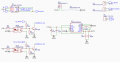
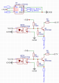
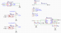
I have the circuit that controls a dc motor using the L9110s motor driver. It is powered by a 1.5V AAA battery that is stepped up by the TI TPS61027DRCR TO 5V. The goal of this circuit is that when the ITR8307/TR8 Optical IR Sensor sees a white stopping plate, the motor no longer moves in the given direction.
I currently have the PCB assembled, however when I press the button to move the motor (the white stopping plate not attached), the motor is not moving at all. I increased the input voltage from 1.5v to 3v using a power supply in case I was maxing out the 200mA current draw, and I am facing the same issue. When I used an ammeter to measure the current flowing to the motor I got nothing 0.000A and originally when using 1.5V and applied a load the voltage would drop to 0V which I assumed meant that the TPS61 was being over demanded.
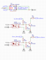
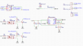
If anyone has any ideas as to what is wrong with my circuit I would be very grateful for any suggestions. One other idea I had was changing the circuit to the second picture to reduce components and potential complications. Thank you!
I have the circuit that controls a dc motor using the L9110s motor driver. It is powered by a 1.5V AAA battery that is stepped up by the TI TPS61027DRCR TO 5V. The goal of this circuit is that when the ITR8307/TR8 Optical IR Sensor sees a white stopping plate, the motor no longer moves in the given direction.
I currently have the PCB assembled, however when I press the button to move the motor (the white stopping plate not attached), the motor is not moving at all. I increased the input voltage from 1.5v to 3v using a power supply in case I was maxing out the 200mA current draw, and I am facing the same issue. When I used an ammeter to measure the current flowing to the motor I got nothing 0.000A and originally when using 1.5V and applied a load the voltage would drop to 0V which I assumed meant that the TPS61 was being over demanded.
If anyone has any ideas as to what is wrong with my circuit I would be very grateful for any suggestions. One other idea I had was changing the circuit to the second picture to reduce components and potential complications. Thank you!
Attachments
-
 130.5 KB Views: 26
 -
 105.4 KB Views: 23