movement sensor not working properly with 12v adapter connected to circuit

Thread Starter

impeham

Joined Dec 8, 2017
16
Hi.

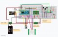
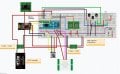
I built a circuit using arduino nano as seen in the attached picture.

There is a strange issue with the movement sensor and i can't figure out why:

If i connect the arduino to my PC with USB cable only, everything works fine (just the LED won't turn on because there is no 12v input). so the movement sensor is working and reacting as expected.

Then i connect the 12v power supply and everything works well except for the movement sensor - it is always 0 - even if there is movement near it. the strange thing is that if i turn on the RGB
LED just a little bit (making it not completely 0,0,0), the movement sensor starts to react as it should.

what could be the cause for this? i want the sensor to work even if the RGB is completely off.
 

Attachments

AlbertHall

Joined Jun 4, 2014
12,347
The only power source for the nano is the USB. When you connected the 12V supply was the usb still connected?
You have no current limit resistors for either the base of the tramsistors or the LED.
 

Thread Starter

impeham

Joined Dec 8, 2017
16
yes it was. i had a mistake in the photo - sorry - adding an updated one to this message.
i also mistakenly said that all works fine with only the USB connection but i meant only for the motion sensor as it is the only one directly connected to the arduino's power.

yes - i had both connected.
 

Attachments

bertus

Joined Apr 5, 2008
22,278
Hello,

How do you power the arduino and the sensor?
None of them are connected to the 5 Volts power source.
Also there are no base resistors on the 2N4401 are missing.
Also there are no current limitimg resistors for the RGB led.

Arduino_nano.png

Bertus
 

Thread Starter

impeham

Joined Dec 8, 2017
16
Hi - thanks. see my post #3 i had a mistake in the first post of the picture and description.

yes i am not using current limiting resistors - do you think it might be related to the problem? everything in the circuit is working well except for the strange issue with the RGB LED (when 12v power is connected)
.
 

bertus

Joined Apr 5, 2008
22,278
Hello,

Imagine the output of the arduino pushing on the 0.7 Volts of the BE connection of the transistor.
Better use some 1K base resistors to protect the arduino.

Bertus
 

Alec_t

Joined Sep 17, 2013
14,335
there are no base resistors - why do i need them?
Because the base-emitter junction looks like a near-short-circuit to the Arduino and will try to suck a lot of current from the Arduino output pin. That could fry the Arduino or the transistor.
 

AlbertHall

Joined Jun 4, 2014
12,347
Because the base-emitter junction looks like a near-short-circuit to the Arduino and will try to suck a lot of current from the Arduino output pin. That could fry the Arduino or the transistor.
And the same with the LEDs, try with 1kΩ in series with each of the three LED pins.
 
I think that you have multiple problems with that layout.

@Alec_t and @bertus have already described the problems with the way you are driving the RGB LED.
In addition to that, I think you have a problem with powering the Nano.

From: https://store.arduino.cc/usa/arduino-nano

The Arduino Nano can be powered via the Mini-B USB connection, 6-20V unregulated external power supply (pin 30), or 5V regulated external power supply (pin 27). The power source is automatically selected to the highest voltage source.


Additionally, when you power the Nano from USB, pin 27 will have 5V OUT (see the schematic here - 5V auto-selector).

Assuming that you have enough current supplied by your 12V out, I recommend that you feed 12V into pin 30 Vin and let the Nano regulate it (you have this pin being fed by your 5V regulator). Also recommend that you not not use pin 27 as a Vout, instead use the output of your 5V regulator for that rail (as you are doing) and leave pin 27 unconnected - powering he movement sensor from the positive +5 rail).
 

Thread Starter

impeham

Joined Dec 8, 2017
16
Thanks i will try that.
just another noob question - i'm trying to understand why there is a need to use current limiting resistor for leds, etc. for example - if a led requires 5v and i'm using 5v DC adapter with it, it should draw as much current as it needs no? why a limit is needed with a resistor?
 

AlbertHall

Joined Jun 4, 2014
12,347
Below is a graph of current versus voltage for varios colours of LED. You can see that as the voltage the current increases very sharply. For only the UV LED is the current less than 100mA at 5V. Your circuit is driving the LEDs with 12V and the current at that voltage would be very large.

The same kind of curve applies to the base-emitter junction of a transistor so again a very large current would flow from the arduino pins to the bases of the transistors.
 

Thread Starter

impeham

Joined Dec 8, 2017
16
the RGB led is a led strip - it requires high current. the arduino pin output is max of 40ma and it is working well with this set up - is there something needs to be fixed?
 

MisterBill2

Joined Jan 23, 2018
18,600
If the motion sensor is the very bottom device in the picture then it is not obvious where the power source is, unless somehow that Arduino board is supplying power to it, which I doubt. LEDs mostly are a forward biased diode and so they have a definite forward voltage at which the current will be correct. When that voltage is exceeded the current will rise very rapidly with the voltage, resulting in excessive power dissipation in the LED, or any diode, for that matter. THAT is why one should use a series current limiting resistor. Of course, there are a few LED devices that include a constant current regulator circuit, and they are very handy to use. Probably you don't have that kind, since they are unusual. OF COURSE the arduino project instructions leave out all of this technical information.
If you have a multimeter the fist step is to verify that the motion sensor module has the correct supply voltage. The next step is to read the data page for the motion sensor and see what the output voltage will be in both the standby and the triggered conditions. Then you can use the meter to verify if the motion sensor output is actually functioning. It might be that it needs either a pull-up resistor or a pull-down resistor. Some outputs are like that, others are not. The data sheet should explain which type it is.
 
Top