Second order passive low pass filter design

Thread Starter

pinkyponky

Joined Nov 28, 2019
373
1k or 1.015k isn't going to make much difference, it's 1.5% and you'll not get an inductor that accurate.
Going back to the table in post #22, if you want to use a 1k source impedance and a 3.3k load impedance, then you should use 8th row (load/source = 3.33) which gives 0.2447 for Cl and 5.31 for Cc.
That gives an inductance of 1.28mH
I found this one
https://4donline.ihs.com/images/Vip...1-1.pdf?hkey=6D3A4C79FDBF58556ACFDE234799DDF0
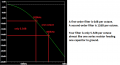
and it has a self-resonant frequency of 1.3MHz, which means that above that frequency it behaves like a capacitor.
That means that if you want to remove frequencies above 1.3MHz it won't work, and a single-order RC filter would work better (and an 2nd order RCRC filter would work better still).
Hello Lan,

I have also calculated and got the same values. :D

RL
3300​
RS
1000​
RL/RS
3,3​
L_coefficient
0,2447​
These values are chosen from the table in the post #22, since I have calculated the ration of RL/RS is 3.3 and n=2 selected.
C_coefficient
5,3126​
L1
0,001285435​
1.28mH
C1
2,56269E-09​
2.56nF
 

Thread Starter

pinkyponky

Joined Nov 28, 2019
373
Taking a Butterworth filter as a example.
Coefficients Cl and CC are both √2
Then C=Cc/(2πfR)
L=Cl.R/(2πf)
for a 3.3k load, zero source impedance and 100kHz cutoff, L=7.4mH C=680pF
for other types of filter, and different source impedance, I’ll have to get out my copy of Zverev.
Is that (Image in the post #22) butterworth filter or RLC lowpass filter?.

As I know this is RLC lowpass filter, why they also mentioned butterworth response.
 

Ian0

Joined Aug 7, 2020
13,132
This is how it performs. Your filter is the red trace. I have added the parasitic capacitance that causes the 1.3MHz self-resonant frequency.
The blue trace is an RCRC filter.
Screenshot at 2022-09-30 17-47-38.png
 

Thread Starter

pinkyponky

Joined Nov 28, 2019
373
You'll get 12dB/oct if you use the Cc and Cl coefficients from the table.
Hi,

Yes, I have calculated by using the coefficients and I simulate the circuit by using those values, but not achieve 12db/oct, see below simulations.

I have 9.18db/octave only.

1664572068078.png
 

Ian0

Joined Aug 7, 2020
13,132
The first octave above the cutoff will rarely be exactly 12dB. 12dB/octave refers to the slope after the line straightens out.
For Bessel filters it will be rather less than 12dB in the first octave, for Chebyshevs it will be rather more.
 

Thread Starter

pinkyponky

Joined Nov 28, 2019
373
There are tables in the same vein for Bessel, Chebyshev, Gaussian, etc.
Thats fine, Is that butterworth filter or RLC filter?. I'm planning to design RLC filter, but I'm confusing that why you guys asked me to follow butterworth response shown in post #22.
 

Thread Starter

pinkyponky

Joined Nov 28, 2019
373
The first octave above the cutoff will rarely be exactly 12dB. 12dB/octave refers to the slope after the line straightens out.
For Bessel filters it will be rather less than 12dB in the first octave, for Chebyshevs it will be rather more.
Not clearly understand,

Please could you explain more, like by drawing on simulation how to measure and from where to where will be measured to find out 'db vs octave'?.
 
Last edited:

Ian0

Joined Aug 7, 2020
13,132
Thats fine, Is that butterworth filter or RLC filter?. I'm planning to design RLC filter, but I'm confusing that why you guys asked me to follow butterworth response shown in post #22.
A Butterworth filter IS an RLC filter, so is a Bessel filter and a Chebyshev.

RLC refers to how you make it (out of a resistor, capacitor and inductor)
A Sallen and Key filter can also be Butterworth, Bessel and Chebyshev - a Sallen and Key is an active filter, usually made with op-amps.

Bessel, Butterworth and Chebyshev refer to how it performs - Bessel has linear phase, Butterworth has flattest response and Chebyshev has the steepest initial roll-off.
 

LvW

Joined Jun 13, 2013
2,029
Thats fine, Is that butterworth filter or RLC filter?. I'm planning to design RLC filter, but I'm confusing that why you guys asked me to follow butterworth response shown in post #22.
Pinkyponky, you clearly must discriminate between (1) form (approximation) of the transfer function like Bessel-Thomson, Butterworth, Chebyshev, Cauer,... and (2) alternative hardware realization (circuit topologies) like passive (RC or RLC) resp. active (Multi-feedback, Sallen-Key, GIC, KHN,....)
 

Thread Starter

pinkyponky

Joined Nov 28, 2019
373
Hello again,

This is how it performs. Your filter is the red trace. I have added the parasitic capacitance that causes the 1.3MHz self-resonant frequency.
The blue trace is an RCRC filter.
View attachment 277423
Thank you, Ian!

1) The requirement of filter circuit to be designed with the components of RLC, so I need to design a circuit according to the requirement.

2) As per requirements I don't have a place to keep height of inductance on the PCB, so I need to reduce the size of inductance. So, what can I do?.

Please can you help me with this?.
 

Ian0

Joined Aug 7, 2020
13,132
Use
Hello again,


Thank you, Ian!

1) The requirement of filter circuit to be designed with the components of RLC, so I need to design a circuit according to the requirement.

2) As per requirements I don't have a place to keep height of inductance on the PCB, so I need to reduce the size of inductance. So, what can I do?.

Please can you help me with this?.
Use the RCRC filter. It performs better than the RLC filter and takes up much less space.
 

MrAl

Joined Jun 17, 2014
13,704
I have selected R1 as a high resistance value because I have an input impedance to the RLC filter and also I have an impedance on the Inductor, so these will affect the signal if I chosen low resistance as a R1, thats's why I have selected the high value of R1.
Can you use a buffer?
 

MrAl

Joined Jun 17, 2014
13,704
Taking a Butterworth filter as a example.
Coefficients Cl and CC are both √2
Then C=Cc/(2πfR)
L=Cl.R/(2πf)
for a 3.3k load, zero source impedance and 100kHz cutoff, L=7.4mH C=680pF
for other types of filter, and different source impedance, I’ll have to get out my copy of Zverev.
i asked specific questions.
 
Top