Facebook
 Google
 GitHub
 Linkedin
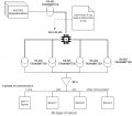
The thing you need to understand is that there is NO standard for serial interface protocol for sensors.
Your RS-485 bus needs to communicate with a common protocol that ALL the nodes understand- they ALL need to work on a common protocol.
You need a node that translates each sensor signal into A COMMON PROTOCOL
Your RS-485 bus needs to communicate with a common protocol that ALL the nodes understand- they ALL need to work on a common protocol.
You need a node that translates each sensor signal into A COMMON PROTOCOL