Facebook
 Google
 GitHub
 Linkedin
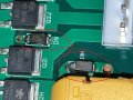
I recently ordered from JLCPCB and after my order arrived I realized a few flyback diodes were in the wrong orientation.
I used my soldering iron at 350c with a small chisel tip and was able to flip each diode to the proper position.
My problem now is each diode is conducting about 2.775v in the reverse bias direction, and all diodes show an almost identical reading of about 2.775v +- 0.005v
If I de solder a diode and test it off the board, my multimeter indicates its working as it should, but as soon as I re solder to the board it gives me reverse bias voltage again
Boards have not been powered at all yet
All diodes are same part number (SS54)
The iron wasn't contacting any diode for more than 5 sec or so
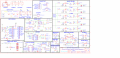
There is no solder bridged underneath the diodes that I can see
PCB Traces are not touching anywhere (verified with gerber and visual inspection of board)
Multimeter indicates diodes are good when tested individually away from the board, even after multiple times soldering/de soldering
Multimeter didn't show these readings before flipping each diode
I'm at a loss as to why, if anyone has any ideas where this odd behavior is coming from it would be greatly appreciated!!
I used my soldering iron at 350c with a small chisel tip and was able to flip each diode to the proper position.
My problem now is each diode is conducting about 2.775v in the reverse bias direction, and all diodes show an almost identical reading of about 2.775v +- 0.005v
If I de solder a diode and test it off the board, my multimeter indicates its working as it should, but as soon as I re solder to the board it gives me reverse bias voltage again
Boards have not been powered at all yet
All diodes are same part number (SS54)
The iron wasn't contacting any diode for more than 5 sec or so
There is no solder bridged underneath the diodes that I can see
PCB Traces are not touching anywhere (verified with gerber and visual inspection of board)
Multimeter indicates diodes are good when tested individually away from the board, even after multiple times soldering/de soldering
Multimeter didn't show these readings before flipping each diode
I'm at a loss as to why, if anyone has any ideas where this odd behavior is coming from it would be greatly appreciated!!