Facebook
 Google
 GitHub
 Linkedin
Hi All,
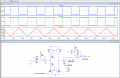
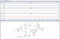
To realise the below circuit I designed a circuit in MultiSim and tried ti simulate. But I'm unable to do so. I would appreciate any help in this regard.


To realise the below circuit I designed a circuit in MultiSim and tried ti simulate. But I'm unable to do so. I would appreciate any help in this regard.