Sanity check of a schematic

Thread Starter

metermannd

Joined Oct 25, 2020
472
MisterBill: The overall purpose is to allow an electric utility to read the meters on its system as well as control interruptible loads (A/C, water heaters, etc.) from the office, using the distribution system itself to carry the data instead of over the air.

The main computer in the office communicates with transceivers that are tied into the equipment in each substation. That part of the system consists of the transceiver, coupling transformer, and high-voltage capacitors - and for obvious reasons, handled by the linemen only. Likewise, there are repeaters present along the longer circuits, and these installations are very similar to capacitor banks that are installed for power factor adjustment - again, handled by the linemen only.

There are two types of endpoint nodes installed at each customer's location.

There is a receive-only unit that cycles interruptible loads at the customer's location (when the utility is in a peak-load or 'contingency' situation regarding capacity, they can selectively cycle loads to reduce the cumulative demand on the system - shaving X megawatts from the system load would be like bringing a peaking plant with a capacity of X megawatts online). These have low-power relays to interrupt the thermostat circuit or high-power relays to interrupt the load directly.

On the other hand, some 'smart' meters can be fitted with a register module that is capable of listening for and responding to messages (polling each meter for its readings and collecting the responses).
For residential applications, the earlier versions of these 'smart' meters for this system consisted of a regular electromechanical meter fitted with electronics in front of the register or in a box between the meter and its socket.
For commercial applications, polyphase meters are already that much deeper than residential meters and adding those electronics would make them stick out too far (not an issue with modern solid-state meters).
The solution in this case is to install a 'pulse initiator' in the polyphase meter (the pulse initiator is an optional meter accessory that has long been used as part of installations to record the peak demand at industrial customer locations). Those pulse initiator leads attach to a transponder like I showed to allow the paired three-phase meters to be read along with the residential meters.
 

MisterBill2

Joined Jan 23, 2018
27,730
OK, now the thread makes more sense to me. The "system" is about wireless meter reading for utility billing purposes. That could be similar to the wireless water meter reading system. I know that our local system once generated a warning about a major leak, after the refilling of a replacement water heater.
I find that THAT level of real time monitoring is a bit spooky!
It also demonstrates that the technology is already available, at least for water meter monitoring.
 

drjohsmith

Joined Dec 13, 2021
1,620
MisterBill: The overall purpose is to allow an electric utility to read the meters on its system as well as control interruptible loads (A/C, water heaters, etc.) from the office, using the distribution system itself to carry the data instead of over the air.

The main computer in the office communicates with transceivers that are tied into the equipment in each substation. That part of the system consists of the transceiver, coupling transformer, and high-voltage capacitors - and for obvious reasons, handled by the linemen only. Likewise, there are repeaters present along the longer circuits, and these installations are very similar to capacitor banks that are installed for power factor adjustment - again, handled by the linemen only.

There are two types of endpoint nodes installed at each customer's location.

There is a receive-only unit that cycles interruptible loads at the customer's location (when the utility is in a peak-load or 'contingency' situation regarding capacity, they can selectively cycle loads to reduce the cumulative demand on the system - shaving X megawatts from the system load would be like bringing a peaking plant with a capacity of X megawatts online). These have low-power relays to interrupt the thermostat circuit or high-power relays to interrupt the load directly.

On the other hand, some 'smart' meters can be fitted with a register module that is capable of listening for and responding to messages (polling each meter for its readings and collecting the responses).
For residential applications, the earlier versions of these 'smart' meters for this system consisted of a regular electromechanical meter fitted with electronics in front of the register or in a box between the meter and its socket.
For commercial applications, polyphase meters are already that much deeper than residential meters and adding those electronics would make them stick out too far (not an issue with modern solid-state meters).
The solution in this case is to install a 'pulse initiator' in the polyphase meter (the pulse initiator is an optional meter accessory that has long been used as part of installations to record the peak demand at industrial customer locations). Those pulse initiator leads attach to a transponder like I showed to allow the paired three-phase meters to be read along with the residential meters.
do we know what actual communication system this unit is following ?

are you wanting to make your own receiver ?
are you wanting to make your own communication over mains system?
 

Thread Starter

metermannd

Joined Oct 25, 2020
472
MisterBill2: Wired, actually. That dBV meter I had a thread about a couple months ago is another component of the system, to assess the signal strength at a given location when troubleshooting reception issues.

drjohnsmith: Not really trying to make anything new, just trying to fit the puzzle pieces together to understand the scheme a bit better. As far as the communications protocol, all I know is that it uses some type of phase-shift keying system to encode and decode the data so it may be a proprietary format. Overall, this is part of a project I began during the "the year of the prolonged cabin fever" when I found a portable terminal for this system on a large auction site. At this point I have gathered almost all the information I can realistically hope to find (there remains one piece of equipment, but it evidently was rare even when new). I mainly want to tidy up loose ends so I can finish satisfying my curiosity and move on to more productive endeavors. :)
 
Last edited:

drjohsmith

Joined Dec 13, 2021
1,620
MisterBill2: Wired, actually. That dBV meter I had a thread about a couple months ago is another component of the system, to assess the signal strength at a given location when troubleshooting reception issues.

drjohnsmith: Not really trying to make anything new, just trying to fit the puzzle pieces together to understand the scheme a bit better. As far as the communications protocol, all I know is that it uses some type of phase-shift keying system to encode and decode the data so it may be a proprietary format. Overall, this is part of a project I began during the "the year of the prolonged cabin fever" when I found a portable terminal for this system on a large auction site. At this point I have gathered almost all the information I can realistically hope to find (there remains one piece of equipment, but it evidently was rare even when new). I mainly want to tidy up loose ends so I can finish satisfying my curiosity and move on to more productive endeavors. :)
have you looked at the different schemes that are / were used ?
then try to match those with what you know from the investigation,
what do you think the "corrected" schematic does ?
 

MisterBill2

Joined Jan 23, 2018
27,730
OK, and interesting indeed!
What appears to make the most sense is a polled device scheme where each meter is called by it's identification code, and then it responds with it's code and it's report. That would require a direct RF link rather than over wires, which avoids the need for any infrastructure accommodation. so the meter reader would still need to travel with the portable system, but a vastly reduced labor effort. The transmit power needed could be much less, and the individual receive sensitivity likewise reduced.
 

drjohsmith

Joined Dec 13, 2021
1,620
@metermannd
there is a nice overview and links on some of the different mains coms systems here

https://en.m.wikipedia.org/wiki/Power-line_communication

wonder does your bit of kit fit into any of these ?

and I wonder, how are you going to do anything with this gear ?

did you also say @metermannd about seeing this gear from which this schematic was made , was not yours so you could not open it ?

then you say its equipment you purchased off an auction site ?

confused
 
Last edited:

Thread Starter

metermannd

Joined Oct 25, 2020
472
Communication is entirely through the distribution system. The carrier that is overlaid onto the 60Hz is one of two frequencies (9.6 kHz and 12.5 kHz), just below the 'long haul low frequency' band in the article. I managed to dump the code for one of the receive-only units and it is definitely some proprietary algorithm...

The output card in the transceiver puts out some SERIOUS amplitude - I hesitate to say the exact value, but I never liked testing those cards, especially the new style with TO-247 MOSFETs (the earlier style used a now-obsolete TO-3 part).
Conversely, the receiver card in the transceiver had to be quite sensitive (I believe the original spec specified a minimum of 1.5 mVpp, but we had to change the spec after the original HP3314 failed; instead of seeking a good used unit, customer adjusted the spec to work with the HP33120 / HP33220 units we had on hand).

A picture is worth a thousand words...

CCU-711.jpg is one of the transceiver units (picture is a 'stock image' I found online some time back before it was superseded by a newer style unit). Left side of the upper rack has the low-voltage P/S, modem, logic, and receiver cards. The right side carries two pairs of output drivers and amplifier cards. The lower rack carries the address / status LED module (and accessory outlet), a coupler card (the unit could handle up to 8, but nobody ever fitted more than 4), and an amplifier selector card. Down under is the RF connector plate with N-type connectors where the cables for the Primary Coupling Assembly attach (the PCA is the actual interface with the distribution system).

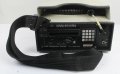
FCT unit.jpg is the unit I picked up off the auction site. I passed it along to someone who wants to set up a museum relating to power and communications after taking the time to reverse-engineer schematics for the innards (at least it kept me busy during the enforced cabin fever days). That person also had one of the CCUs and a repeater, and I have since completed schematics of both.

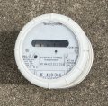
MCT-210.jpg is the meter version of the transponder that I showed in post 12 (this is the 'residential' style I spoke of in post 21, the unit in post 12 is an interior view of the 'commercial' version).

CCU-711.jpg MCT-210.jpg FCT unit.jpg
 

Thread Starter

metermannd

Joined Oct 25, 2020
472
A postscript: I eventually acquired the unit with this circuit board and with it in hand, the wiring of the board and almost all the part values were spot on.
There were only two errors; I misread the multiplier band on R1 (it was 200 ohms, not 2) and designators on P2 and P3 were swapped.
 

drjohsmith

Joined Dec 13, 2021
1,620
A postscript: I eventually acquired the unit with this circuit board and with it in hand, the wiring of the board and almost all the part values were spot on.
There were only two errors; I misread the multiplier band on R1 (it was 200 ohms, not 2) and designators on P2 and P3 were swapped.
Well done and thanks for getting back to the forum
 
Top