Rom memory

Thread Starter

abhimanyu143

Joined Aug 25, 2014
211
hello,
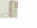
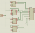
I need help to understand Rom memory. rom memory is memory that store program. we can only read rom memory. example: rom 16x4
4 data line
4 address line

Address -----> Data
0000 -------> 0001 store Data 0001 at address 0000
0001 -------> 0011 store data 0011 at address 0001
0010 -------> 0110 store data 0110 at address 0010
0011 -------> 0010 store data 0010 at address 0011
0100 -------> 1100 store data 1100 at address 0100
0101 -------> 0100 store data 0100 at address 0101
0110 -------> 0111 store data 0111 at address 0110
0111 -------> 0101 store data 0101 at address 0111
1000 -------> 0000 store data 0000 at address 1000
1001 -------> 1000 store data 1000 at address 1001
1010 -------> 1011 store data 1011 at address 1010
1011 -------> 1001 store data 1001 at address 1011
1100 -------> 1101 store data 1101 at address 1100
1101 -------> 1111 store data 1111 at address 1101
1110 -------> 1010 store data 1010 at address 1110
1111 -------> 1110 store data 1110 at address 1111

That's just example I am not sure that table is right for Rom memory . I just want to confirm that rom memory work on that basic
 
Last edited:

Thread Starter

abhimanyu143

Joined Aug 25, 2014
211
welcome ,
we can store data at address . xxxx may be anything
its just example
Address -----> Data
0000 -------> xxxx example // store Data 0001 at address 0000
0001 -------> xxxx example //store data 0011 at address 0001
0010 -------> xxxx example //store data 0110 at address 0010
0011 -------> xxxx example //store data 0010 at address 0011
0100 -------> xxxx example // store data 1100 at address 0100
0101 -------> xxxx example // store data 0100 at address 0101
0110 -------> xxxx example // store data 0111 at address 0110
0111 -------> xxxx example //store data 0101 at address 0111
1000 -------> xxxx example // store data 0000 at address 1000
1001 -------> xxxx example //store data 1000 at address 1001
1010 -------> xxxx example // store data 1011 at address 1010
1011 -------> xxxx example //store data 1001 at address 1011
1100 -------> xxxx example // store data 1101 at address 1100
1101 -------> xxxx example //store data 1111 at address 1101
1110 -------> xxxx example // store data 1010 at address 1110
1111 -------> xxxx example // store data 1110 at address 1111
 

ErnieM

Joined Apr 24, 2011
8,377
"ROM" or Read Only Memory is a term that is some 50 or 60 years old and has changed in meaning several times, so knowing what your ROM could be is vital in answering your question. "ROM" is a fuzzy word who's meaning depends on where it is used. It is not a precise term.

Are you just asking for some general information or do you have something specific in mind?

rom memory is memory that store program.
Yes, a program is typically kept in ROM, but this restriction depend on where and how ROM is used.

PROM (where the P means the ROM chip can be "Programmed" once) was developed in the 1950's to store constants. Even in the smallest microcontrollers constant data need to be stored in ROM as there may be no other place to put it.
we can only read rom memory.
Usually ROM can only be read. It depends on the technology used to make the ROM. The newer types generally allow for changes to be made, such as EEPROM (Electrically Erasable Programmable Read-Only Memory) or Flash memory.

Today's ROM allows changes almost at will, opening up applications where say a micro can reprogram itself (using a small program called a boot loader) so the main program can be updated.

Also, since the days of mask ROM are long over (where a set of chips were programmed during manufacture with custom wafer mask patterns) all ROM chips need to be written to at least once to get the initial data in there.

example: rom 16x4
4 data line
4 address line

...just want to confirm that rom memory work on that basic
You could put such information into a ROM.
 

Thread Starter

abhimanyu143

Joined Aug 25, 2014
211
"ROM" or Read Only Memory is a term that is some 50 or 60 years old and has changed in meaning several times, so knowing what your ROM could be is vital in answering your question. "ROM" is a fuzzy word who's meaning depends on where it is used. It is not a precise term.

Are you just asking for some general information or do you have something specific in mind?


Yes, a program is typically kept in ROM, but this restriction depend on where and how ROM is used.

PROM (where the P means the ROM chip can be "Programmed" once) was developed in the 1950's to store constants. Even in the smallest microcontrollers constant data need to be stored in ROM as there may be no other place to put it.

Usually ROM can only be read. It depends on the technology used to make the ROM. The newer types generally allow for changes to be made, such as EEPROM (Electrically Erasable Programmable Read-Only Memory) or Flash memory.

Today's ROM allows changes almost at will, opening up applications where say a micro can reprogram itself (using a small program called a boot loader) so the main program can be updated.

Also, since the days of mask ROM are long over (where a set of chips were programmed during manufacture with custom wafer mask patterns) all ROM chips need to be written to at least once to get the initial data in there.


You could put such information into a ROM.
Thanks for useful information. I am using 27256 Ic as EpROM. I want to connect EPROM with program counter. I searched on internet. I looked 74LS90. Can I use 74LS90 Ic as program counter , or I need another Ic
how to connect two IC ROM and program counter together ?
 

Attachments

ErnieM

Joined Apr 24, 2011
8,377
It sure sounds like you are going to build your own computer from scratch.

The 27256 was a workhorse in its time and should work well. They do need a n ultraviolet light to erase the device. The inputs look TTL compatible so the 74LS device should drive them.

However, the 74LS90 is a decade counter, and you want a binary counter, and a binary counter with both a clear and preset-able inputs. You need the clear for when you power this on. You need the preset so your code can perform a jump.

Last, if you use 4 bit counters you will need 4 of them cascaded together to get a total of 4x4=16 address lines. That more than covers the 15 address lines of the EPROM.
 

Thread Starter

abhimanyu143

Joined Aug 25, 2014
211
It sure sounds like you are going to build your own computer from scratch.

The 27256 was a workhorse in its time and should work well. They do need a n ultraviolet light to erase the device. The inputs look TTL compatible so the 74LS device should drive them.

However, the 74LS90 is a decade counter, and you want a binary counter, and a binary counter with both a clear and preset-able inputs. You need the clear for when you power this on. You need the preset so your code can perform a jump.

Last, if you use 4 bit counters you will need 4 of them cascaded together to get a total of 4x4=16 address lines. That more than covers the 15 address lines of the EPROM.
i have done some connection using 74ls90 Ic but there is no clear and preset input
I have attached the circuit. please look following circuit
 

Attachments

takao21203

Joined Apr 28, 2012
3,702
its a nonsense circuit. 7490 is a decimal counter.
And you dont carry over the high bits neither.

You need a counter with a carry output, and hexadecimal counting.
 

ErnieM

Joined Apr 24, 2011
8,377
You have a few things right and a few things wrong. The 74LS90 just can't work here, you need something like a 74LS163 which is a pure binary counter. See if you can figure out how to cascade them so when the first chip's count goes from 15 back to zero the second chip also makes a count, and so on.

Also, look at U4 Q3 output: you have it grounded. Never do that to an output, unused outputs are left to float (unconnected). Most inputs need a connection, either to ground or Vcc depending on the function.
 

Thread Starter

abhimanyu143

Joined Aug 25, 2014
211
its a nonsense circuit. 7490 is a decimal counter.
And you dont carry over the high bits neither.

You need a counter with a carry output, and hexadecimal counting.
as you said I did google for hexadecimal counter. I looked MC 10136 counter with a carry output, and hexadecimal counting
 
Last edited:

Thread Starter

abhimanyu143

Joined Aug 25, 2014
211
You have a few things right and a few things wrong. The 74LS90 just can't work here, you need something like a 74LS163 which is a pure binary counter. See if you can figure out how to cascade them so when the first chip's count goes from 15 back to zero the second chip also makes a count, and so on.

Also, look at U4 Q3 output: you have it grounded. Never do that to an output, unused outputs are left to float (unconnected). Most inputs need a connection, either to ground or Vcc depending on the function.
Can I use MC 10136 ?

Cin S1 S2 Operating Mode
X L L Preset (Program)
L L H Increment (Count Up)
H L H Hold Count
L H L Decrement (Count Down)
H H L Hold Count
X H H Hold (Stop Count)
Also I have attached datasheet
 

Attachments

ErnieM

Joined Apr 24, 2011
8,377
You can probably use that part, but what you've already done is mix logic families, and you've only pickled two parts!

A logic family is crafted to work with everything else in the family. When you mix families you have to take extra care, and sometimes use extra circuitry to get them to work together.

If you start with a TTL family part then stick to that family.
 

ErnieM

Joined Apr 24, 2011
8,377
This is a somewhat different topic then where you started, but another piece to your puzzle.

If I needed to shuffle data between several registers I would start with registers with tri-state outputs. These outputs can disconnect themselves so two or more outputs can be tied together safely, as long as only one at a time is turned on.

To load between registers you connect all the like input and outputs together. To load from say register 1 to 4 you enable just the output of reg 1, then strobe reg 4 to input this data from reg 1.

Generally, this concept is what how a "computer bus" is defined.

Do you have any material on computer architecture, about how to build the central processing unit?
 

absf

Joined Dec 29, 2010
1,968
Hi Abhimanyu,

ErnieM is right.... You can actually implement the registers and Accumulator with SRAM e.g. 2114 (1Kx4) for 4 bit data bus OR 6116 (2Kx8) for 8 bit data bus. You can dedicate address A0-A2 for R0-R6 and use the last address '111' for Aaccumulator. The rest of the unused addresses are connected to ground. By adding a latch as "Temp Register" connected to the data lines of the memory, the data from any one of the registers can be read to "Temp Register" on one clock and write to another register on the next clock from "Temp Register".

The point is microcontroller circuit designs are very flexible. You can design it any way you wanted provided you understand the datasheets of different logic family and be familiar with them.

To answer you question above......

In your circuit, the contents of "Register" can be moved from "Accumulator" and vice verse. If you want to move the contents of "immediate data" to the "Accumulator" then you'd need a 2-1 mux to select between the "Register" & "immediate data". BTW, I assume the data for the "immediate data" comes from the data lines of the program ROM.

So assuming the following instructions are executed:

Code:
1 - MOV A, R1           ;content of R1 to Acc
2 - MOV R1,A            ;content of A to R1
3 - MOV A,#5            ;literal 5 is loaded to A
I'll get a simple schematic ready on next post as I have not completed it yet.

Allen
 

Thread Starter

abhimanyu143

Joined Aug 25, 2014
211
This is a somewhat different topic then where you started, but another piece to your puzzle.

If I needed to shuffle data between several registers I would start with registers with tri-state outputs. These outputs can disconnect themselves so two or more outputs can be tied together safely, as long as only one at a time is turned on.

To load between registers you connect all the like input and outputs together. To load from say register 1 to 4 you enable just the output of reg 1, then strobe reg 4 to input this data from reg 1.

Generally, this concept is what how a "computer bus" is defined.

Do you have any material on computer architecture, about how to build the central processing unit?
I Don't Know about computer architecture. But I have some material on cpu for controller I have visited on some web site. I have read some material. I have some PDF file

Now I have circuit for program counter , program memory and I have Instruction register I want to add some register. I think I have to use instruction decoder, that will connected with output of instruction register
so that circuit will fetch decode and execute following code
Code:
1 - MOV A, R1 ;content of R1 to Acc
2 - MOV R1,A ;content of A to R1
3 - MOV A,#5 ;literal 5 is loaded to A
 

Thread Starter

abhimanyu143

Joined Aug 25, 2014
211
Hi Abhimanyu,


I'll get a simple schematic ready on next post as I have not completed it yet.

Allen
Hello Allen ,
I am waiting for your schematic. I think, that schematic can help me lot, once I get the simple idea , I can add another function
 

absf

Joined Dec 29, 2010
1,968
vead's imm data.PNG
This is the schematic for executing the above 3 instructions that I mentioned.

The truth table for the conditions of S, Y, Z, T is in the picture attached...

BOOK1.png
I have not tested it on the proteus sim. So just use it as a reference only. The S, Y, Z, T can be controlled by the outputs of the instruction decoder.

Allen
 
Top