RF transistor oscillator

Thread Starter

Zeeus

Joined Apr 17, 2019
616
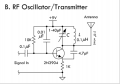
Please explain this circuit.. there's no explanation in book

4.7pf provides positive feedback?
How does the circuit work? Thanks

Tried for 90Mhz capacitor inductor combination but did not work..no oscillation..The LC seemed to be ringing but maybe no enough feedback to make it oscillate

Enlighten TS
Thanks
 

Attachments

Danko

Joined Nov 22, 2017
2,168
C1 is path for feedback: Bottom_L1C2 - C3 - EB_Q1 - C1 - Top_L1C2.
When R1 small - Q1 fully ON, no oscillation.
When R1 big - Q1 only slightly ON, too small collector current for oscillation.
Best for oscillation value R1 exists, which you should to find.
 

LvW

Joined Jun 13, 2013
2,026
No - C1 is not for feedback.
The tank circuit L1-C2 has maximum resistance at w=wo and we have the required positive feedback from the collecor to the emitter via C3.
Hence, the the emitter acts as an input for the BJT - which means: The BJT works in common-base configuration - and the base must be at signal ground. THIS is the task of C1 (grounding the base ac wise).
In common-base configuration we have no signal inversion between input and outout - therefore, C3 provides positive feedback.
 

Thread Starter

Zeeus

Joined Apr 17, 2019
616
No - C1 is not for feedback.
The tank circuit L1-C2 has maximum resistance at w=wo and we have the required positive feedback from the collecor to the emitter via C3.
Hence, the the emitter acts as an input for the BJT - which means: The BJT works in common-base configuration - and the base must be at signal ground. THIS is the task of C1 (grounding the base ac wise).
In common-base configuration we have no signal inversion between input and outout - therefore, C3 provides positive feedback.
Please explain more..Thanks
 

LvW

Joined Jun 13, 2013
2,026
Please explain more..Thanks
Didn`t I explain the principle?
Each oscillator needs an active device (in your case a BJT) and a frequency-selective POSITIVE feedback which can fulfill barkhausens oscillation condition at one single frequency only.
For this purpose, we have a parallel resonant circuit (tank) connected at the output of the BJT and a feedback path to the non-inverting input of the transistor (emitter).
However, it is important to habe enough gain to fulfill the oscillation condition (loop gain larger than unity).
This requires to have the ability to increase/decrease the gain...which can be done using different values for the base resistor. This resistor determines the transconductance gm of the transistor and - hence - the gain.
 

Thread Starter

Zeeus

Joined Apr 17, 2019
616
@Zeeus, you can try this more powerful 100 MHz generator:
View attachment 183328


I successfully use its for feedback. May I?
Tried the circuit but unfortunately not working..changed C3 to variable cap but no show..guess is price for not understanding circuit

You know the sound from power supply (adapter ac to dc) when there is short across it..can hear that sound

Dunno
 

MrAl

Joined Jun 17, 2014
13,704
Can you use the 2N3904 effectively at 90MHz ?

I would use a transistor that has good gain at 100MHz and made for RF.
PN5179 (500MHz oscillator 2N3904 cant touch) or MPS5179
2N5770 maybe
 
Last edited:

Danko

Joined Nov 22, 2017
2,168
Tried the circuit but unfortunately not working..changed C3 to variable cap but no show..guess is price for not understanding circuit
You know the sound from power supply (adapter ac to dc) when there is short across it..can hear that sound
Interesting...
Do you use oscilloscope?

1. Measure current consumes by oscillator.
2. Circuit is shorted somewhere? Check it.
3. If it is powerful oscillator, then, even transistor is shorted,
current should be not more than 90mA, because of resistor R3.
4. Check transistor, replace if needed.
5. For safety use resistor and capacitor before oscillator:
upload_2019-8-7_16-49-30.png
 
Last edited:

Janis59

Joined Aug 21, 2017
1,894
This is the common base circuit at AC with grounded base (via C1). Inspite of by DC being the normal common emitter. The emitter is the input and tank to collector point is the output. C3 is the loop capacitor. From it value is dependant a oscillation regime - mild or hard. Circuit itself is uniquely stable and works well with all possible values of component nominals, transistors and voltages. Thus R2 is playing the same role as general CE amplifier identical element, but attitude X(C1) / R2 is that factor of loop strength.
 

Thread Starter

Zeeus

Joined Apr 17, 2019
616
Interesting...
Do you use oscilloscope?

1. Measure current consumes by oscillator.
2. Circuit is shorted somewhere? Check it.
3. If it is powerful oscillator, then, even transistor is shorted,
current should be not more than 90mA, because of resistor R3.
4. Check transistor, replace if needed.
5. For safety use resistor and capacitor before oscillator:
View attachment 183386
Hi thanks..
for 1) as it is not oscillating, you mean dc current? the emitter was about 0.9v and with 91 ohms so about 10mA..same as your image

I will do 4 and 5 later : want to read a little on

If you can check attached image : made this transmitter days ago, it worked if I touch the capacitor to ground plane but with more heat on transistor :
Used electret mic with audio amplifier at input then could pick up from radio but trying to use aux cord and also want to increase the frequency : it is meant to oscillate in fm band but for me it was about 70 MHZ and radio starts from 88 MHZ : Please how to increase frequency ?

Don't really understand the circuit but understand a little and reading on it
Anyways, thanks for your input : makes me understand reading more

Thanks thanks

Changed the values of the emitter inductors (what do they do?) but highest was 80 MHZ
R4 and R5 set bias and the capacitor at the base makes it at ground

C6 is for positive feedback yh? the output is from emitter ::: what sets the oscillation for capacitance? C6?

ignorant : read
 

Attachments

Last edited:

Thread Starter

Zeeus

Joined Apr 17, 2019
616
This is the common base circuit at AC with grounded base (via C1). Inspite of by DC being the normal common emitter. The emitter is the input and tank to collector point is the output. C3 is the loop capacitor. From it value is dependant a oscillation regime - mild or hard. Circuit itself is uniquely stable and works well with all possible values of component nominals, transistors and voltages. Thus R2 is playing the same role as general CE amplifier identical element, but attitude X(C1) / R2 is that factor of loop strength.
you have something else to add :) Yes you do. and we are talking about post 6 correct?

Thanks
 

Danko

Joined Nov 22, 2017
2,168
Changed the values of the emitter inductors (what do they do?) but highest was 80 MHZ
R4 and R5 set bias and the capacitor at the base makes it at ground
C6 is for positive feedback yh? the output is from emitter ::: what sets the oscillation for capacitance? C6?
For increase frequency you can:
Add inductors in parallel with existing. It will lower inductance. 3 inductors and capacitor C6 are bank.
In the same time you can lower value of capacitor C6. Feedback signal is going from capacitor C7.
It is Colpitts oscillator. See https://forum.allaboutcircuits.com/threads/common-base-colpitts-oscillator.72724/
BTW, inductors are in collector, not in emitter. Rotate paper on 180 degree and you will have right view.
 
Last edited:

Thread Starter

Zeeus

Joined Apr 17, 2019
616
For increase frequency you can:
Add inductors in parallel with existing. It will lower inductance. 3 inductors and capacitor C6 are bank.
In the same time you can lower value of capacitor C6. Feedback signal is going from capacitor C7.
It is Colpitts oscillator. See https://forum.allaboutcircuits.com/threads/common-base-colpitts-oscillator.72724/
BTW, inductors are in collector, not in emitter. Rotate paper on 180 degree and you will have right view.
Thanks, reading post
C7 is for feedback?

Also, the circuit in post 14 is to bypass high frequency (cap C1) signals 31 hz cutoff? what more is it for?
The tuned collector circuit makes the voltage across this C1 oscillate?
why post 14 circuit?
 
Last edited:
Top