Also, the circuit in post 14 is to bypass high frequency (cap C1) signals 31 hz cutoff? what more is it for?
The tuned collector circuit makes the voltage across this C1 oscillate?
why post 14 circuit?
Thanks, reading post
C7 is for feedback?
Also, the circuit in post 14 is to bypass high frequency (cap C1) signals 31 hz cutoff? what more is it for?
The tuned collector circuit makes the voltage across this C1 oscillate?
why post 14 circuit?
C7 with C6 in series are voltage divider, so only lower part of tank's RF voltage applies to E-B transition of Q1.
Circuit in post 14 prevents oscillator components from damage if something will accidentally shorted while you experiment with them.
RE: Zeeus
""Thanks thanks. Changed the values of the emitter inductors (what do they do?) but highest was 80 MHZ""
Wow!! Where You see the inductor in emitter!!!!!!!!!!!! Probably that is the core-reason why it not work.
The max freq is depending on tank first, but heavily deviated by transistor itself. It MUST have a f(T) at least few-fold higher as f(osc) and have a C(ce) less than those external cap between col & em.
If still not generate, explore the divide factor for emitter cap against loop cap. Knowing the emitter resistor ought be capable to calc the K(u). If less than 1 then never will oscillate, must be over 1, but just just, very slightly. For this reason may recomend to substitute for the moment those loop cap with trimmer and adjust for best result, measure it and then put back the "normal" cap.
Last, many caps are not capable to work on anything over few MHz. What type You use there, is it RF capable? If dielectric is not NP0, P100, N33, N75, You probably have a trouble. If it is X7R, X5R, Y5V, Z5U You sure have a trouble at that frequencies.
P.S.
What are DC regimes?
Via c-e must flow some 0,1...10 mA. If no, You have found the reason of problem.
Betw base and emitter MUST be 0,6...0,7V. If less, Your transistor`s fight is over. Burry it. If more, Your`s transistor`s fight is over. Burry it.
Measure V between C and E, must be about half of Vcc. If under, squeeze biasing more closed. If over, make base divider more opened.
Janis, you cannot bias the RF oscillator circuit so that its Vce is half of the power supply voltage because the coil has an extremely low resistance. The collector will be at the supply voltage and the RF signal will swing above and below its voltage as shown in my sim.
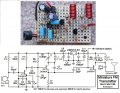
Many threads about somebody making a simple FM transmitter that does not work had their circuit built on a solderless breadboard with its gobs of stray capacitance and inductance between its many rows of contacts and wires all over the place.
I made my FM transmitter compactly on stripboard and it works perfectly.
I added a 5V low dropout voltage regulator for the preamp and RF oscillator so that they work properly as the battery voltage runs down
I added an RF amplifier to isolate the LC tuned circuit from varying stray capacitance at the antenna.
I added pre-emphasis like all FM radio stations use so that it sounds great.
OP watch some videos on Colpitt's and Hartley oscillator's,. A tank circuit on it's own will lose energy and stop, like a mass on a spring, or pendulum, swig, etc.. But the transistor, as a changeable input/output device, and a feedback loop, provides a way to keep adding energy back into the tank circuit, if desired.
I suspect that the radio frequency is 70MHz to 80MHz because the circuit is probably built on a solderless breadboard with added capacitance between the rows of contacts and wires all over the place causing more capacitance than the tiny amounts needed in the circuit.
Quote: "Tried the circuit but unfortunately not working..changed C3 to variable cap but no show..guess is price for not understanding circuit
You know the sound from power supply (adapter ac to dc) when there is short across it..can hear that sound"
Then it is transmitting mains hum picked up by an unshielded audio cable or the breadboard's rows of contacts and wires all over the place.
The circuit I posted works perfectly because its is built very compactly with extremely short wires including the very short wires between the microphone to the preamp transistor.
Audioguru's advice can't be repeated enough, but rather than repeat it, I suggest you read it again carefully.
One common problem with some simple transistor circuits is mis-identifying the transistor leads. For example, somebody once sold me some "2N2222" transistors that the wrong pin-out, for another if you accidentally swap the emitter and collector on a 2N3904 it will test ok with a diode tester but have enough bandwidth to oscillate and might simply act like a 6V Zener diode when power is applied to the circuit.
Make sure you know who made that transistor and check your wiring against the manufacturer's datasheet for that transistor.
I'd also test the transistor first with low voltage to make sure the gain is within reason. That proves it works and the pinout is right. A multimeter that has a transistor socket might work for this.
 Facebook
 Google
 GitHub
 Linkedin