Facebook
 Google
 GitHub
 Linkedin
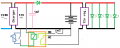
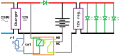
@MisterBill2 There should be no need to connect the NO. When the charger is operating the coil remains energized and the LED's are isolated from the battery. When the charger shuts down the relay will drop out and the NC will close, thus powering the LED's.
I'm in agreement with Bill - you don't want a 12V regulator, but rather a simple resistor to limit the current to the LED's.
You mention that you understand LED's are "Current" driven, not "Voltage". LED's have a characteristic known as Vf, or "Forward Voltage". We don't know what the Vf is on your LED Lamps. If they're designed to operate on 12V then you don't even need a resistor. There's already some sort of current limiting circuitry built into the lamps. Besides, a 12V regulator generally needs a "Head" voltage (some volts higher than the regulated output). Haven't messed with regulators in quite a while, so off hand I'll take a wild guess and say that for a 12V regulator to work the input voltage needs to be 2 to 3 volts higher than the regulated output (Head voltage 2 to 3V). That's probably wrong, but for the sake of argument, a 12V regulator powered from a 12V battery doesn't work. At some point the battery voltage is going to drop, and you won't have 12 regulated volts supplying the LED's.
SW1 ? ? ? Why the switch? Is that so you can test the lamps? So you can turn them on if needed? Personally I see it as a wasted use of excess components. The variable resistor - I get that from earlier comments that you want to be able to trigger the lighting during "Brown-Outs" (BO). If you have a lot of BO in your shop then I can see its usefulness. However, by switching the DC side with a relay as opposed to the proposed AC relay - the DC relay in general is not designed for long term operation. By "Long Term" I mean being active for days, weeks, months, etc. An AC relay is designed for that sort of operation.
As Bill pointed out - a "Wink-Out", where the lights flash off for half a second or so - with the charger controlling the relay, there's a likelihood that during such WO's the LED's will not flash on. The charger will probably have a capacitance on its output that will tend to carry the output for a few seconds. MY 13.8V PS can power an LED (single 5mm type) for a good 30 to 40 seconds after I've switched it off. YOUR LED's at 12V will probably continue to run for 2 or 3 seconds after switching the PS off. (my PS).
My opinion (and opinions are like arseholes, everybody has one and many stink) is that running an AC relay on the mains is the way to go. When power BO's, lights may or may not come on. But when power fails outright the lights will definitely come on. As for using a DC relay and a diode to block reverse current from holding the relay active - that's a workable solution. But I don't know, and don't think it would bother the charger. However, the presence of the DC relay on the charger might cause issues. Batteries have ESR (Equivalent Series Resistance). The smart charger may depend on reading that ESR. The presence of the relay will definitely confuse that aspect of the charger. Which is another reason why I would opt for a mains controlled relay.
I'm in agreement with Bill - you don't want a 12V regulator, but rather a simple resistor to limit the current to the LED's.
You mention that you understand LED's are "Current" driven, not "Voltage". LED's have a characteristic known as Vf, or "Forward Voltage". We don't know what the Vf is on your LED Lamps. If they're designed to operate on 12V then you don't even need a resistor. There's already some sort of current limiting circuitry built into the lamps. Besides, a 12V regulator generally needs a "Head" voltage (some volts higher than the regulated output). Haven't messed with regulators in quite a while, so off hand I'll take a wild guess and say that for a 12V regulator to work the input voltage needs to be 2 to 3 volts higher than the regulated output (Head voltage 2 to 3V). That's probably wrong, but for the sake of argument, a 12V regulator powered from a 12V battery doesn't work. At some point the battery voltage is going to drop, and you won't have 12 regulated volts supplying the LED's.
SW1 ? ? ? Why the switch? Is that so you can test the lamps? So you can turn them on if needed? Personally I see it as a wasted use of excess components. The variable resistor - I get that from earlier comments that you want to be able to trigger the lighting during "Brown-Outs" (BO). If you have a lot of BO in your shop then I can see its usefulness. However, by switching the DC side with a relay as opposed to the proposed AC relay - the DC relay in general is not designed for long term operation. By "Long Term" I mean being active for days, weeks, months, etc. An AC relay is designed for that sort of operation.
As Bill pointed out - a "Wink-Out", where the lights flash off for half a second or so - with the charger controlling the relay, there's a likelihood that during such WO's the LED's will not flash on. The charger will probably have a capacitance on its output that will tend to carry the output for a few seconds. MY 13.8V PS can power an LED (single 5mm type) for a good 30 to 40 seconds after I've switched it off. YOUR LED's at 12V will probably continue to run for 2 or 3 seconds after switching the PS off. (my PS).
My opinion (and opinions are like arseholes, everybody has one and many stink) is that running an AC relay on the mains is the way to go. When power BO's, lights may or may not come on. But when power fails outright the lights will definitely come on. As for using a DC relay and a diode to block reverse current from holding the relay active - that's a workable solution. But I don't know, and don't think it would bother the charger. However, the presence of the DC relay on the charger might cause issues. Batteries have ESR (Equivalent Series Resistance). The smart charger may depend on reading that ESR. The presence of the relay will definitely confuse that aspect of the charger. Which is another reason why I would opt for a mains controlled relay.