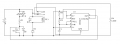
Reverse Polarity flashing LED

LDC3

Joined Apr 27, 2013
924
I think you are confused. A diode does not light up. An LED (light emitting diode) lights up. A diode is used to prevent current from flowing in the reverse direction. An LED will also prevent current in the reverse direction, but the voltage limit (before it is damaged) is usually much lower then for a diode.
 

Thread Starter

liteace

Joined Mar 7, 2012
171
Thanks, Im always confused :confused:
I know the difference between the normal diode and the LED, this circuit has a green LED for power and a red LED that is on when the 5 min timer is on and off when it has finished. What I would like to do is replace the green power LED with a dual color LED that will flash red if the polarity is reversed, there is no room for a 3rd LED but what I would also like to do is make sure that no reversed power can get to the main circuit, Ive read that it will waste power in voltage drop across the diode


Thanks again
 

LDC3

Joined Apr 27, 2013
924
Thanks, Im always confused :confused:
I know the difference between the normal diode and the LED, this circuit has a green LED for power and a red LED that is on when the 5 min timer is on and off when it has finished. What I would like to do is replace the green power LED with a dual color LED that will flash red if the polarity is reversed, there is no room for a 3rd LED but what I would also like to do is make sure that no reversed power can get to the main circuit, Ive read that it will waste power in voltage drop across the diode


Thanks again
When I get home later, I will see about a schematic for you.
 

LDC3

Joined Apr 27, 2013
924
Here is the schematic I said I would make.

I believe that it will work. The MOSFET is a n-channel enhancement mode type which is off unless there is a gate voltage. Note the orientation of the source and drain. The drain is towards the bottom and the source is towards the top. The gate is driven by the output of the 555, which is only on if the battery is connected backwards. The diode is there so the LED will light green.
 

Attachments

Thread Starter

liteace

Joined Mar 7, 2012
171
Thank you very much for that, as per usual there are a couple of parts I dont understand, The dual color LED's I have, have got 3 pins, do I just connect pin 2 (cathode) to earth side (D1). Ive got here :

C1, 1uF 63v
D2, 3 & 4. 1N5818
R1, 680
R2, 1K
R3 470K

I have here 2 new IRFZ44N will 1 of those be OK for Q1, Im assuming that R4 is the main circuit ground side relay switch

Thanks again
 

LDC3

Joined Apr 27, 2013
924
The items you listed should work. I was assuming that the dual LED only had 2 leads and they were connected in reverse polarities. With a common cathode, the wiring is a little different. My first attempt didn't work out correctly, I will need to think about it.
 

Thread Starter

liteace

Joined Mar 7, 2012
171
Thanks for all the info, I'll wait patiently, Ive got everything set out here, bag of components and my breadboard all ready for test

Thanks Again
 

LDC3

Joined Apr 27, 2013
924
Unfortunately, the 3 lead dual LED will not work in this configuration. Here is a 2 lead dual LED that will work in the schematic. Connect the red lead to the resistor (for the cathode of the green LED) and the black lead to the upper power rail (for the cathode of the red LED).
Good luck.
 
Top