Reverse Polarity flashing LED

Thread Starter

liteace

Joined Mar 7, 2012
171
Hi All, would this be poss. I want to build a little circuit with a dual color led for reverse polarity protection, red flashing when polarity reversed and fixed green when polarity correct.
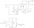
I have looked at and going to build the circuit using the P-channel FET + resistor + diode, how & what else would I need to get the LED to flash red

Thanks
 

wayneh

Joined Sep 9, 2010
17,495
I think MrChips means anti-parallel for the flashing red LED.

But this won't actually provide any protection, only an indication that the polarity is wrong. Is that what you are looking for?
 

Thread Starter

liteace

Joined Mar 7, 2012
171
I need protection as well, I have found a couple of basic circuits using FET + resistor + diode, this is ideal for what I need. This little 555 timer circuit I have already has 2 LED's one for power and one for time, what I would like to do is replace the power LED with a dual color LED that I could incorporate into it some how
 

WBahn

Joined Mar 31, 2012
29,932
As MrChips said, get a flashing red LED and a green LED. Put them antiparallel to each other with appropriate current limiting resistors. Then put a diode in series with your output for protection. Why build a circuit to make an LED flash when you can buy a flashing LED with a 1Hz flash rate for less than a quarter?
 

Thread Starter

liteace

Joined Mar 7, 2012
171
Would this work using a 555 timer and a relay, its a couple of circuits i found and just added them together, the black crossed out part was one of the original circuits
Red flashing with reverse polarity and fixed on green with correct polarity
 

Attachments

Last edited:

Thread Starter

liteace

Joined Mar 7, 2012
171
As MrChips said, get a flashing red LED and a green LED. Put them antiparallel to each other with appropriate current limiting resistors. Then put a diode in series with your output for protection. Why build a circuit to make an LED flash when you can buy a flashing LED with a 1Hz flash rate for less than a quarter?


Why build it, it just gives me a little more experience and keeps my brain ticking over. I read somewhere that that putting a diode in series will cause a voltage drop, is that true
 

absf

Joined Dec 29, 2010
1,968
From your circuit, the relay doesnt operate when the polarities are correct (positive at top and negative at bottom) so you're getting 12V through the NC contacts.

When the battery polarities are wrong, the relay operates. But that would cause a problem. The +12V and Gnd are reversed so your 555 Vcc (pin 8) is getting 0V and GND (pin 1) is getting +12V, so your 555 would not work to flash the red LED. Some mod has to to done to solve this problem.

Allen
 

Thread Starter

liteace

Joined Mar 7, 2012
171
Well spotted Thank you, i would have been banging my head on the wall thinking why does this not work, would adding a few more diodes somewhere help + problem with common cathode on the 3 pin LED, any suggestions
 
Last edited:

Thread Starter

liteace

Joined Mar 7, 2012
171
Thanks, I dont need it to cut power to the 555, the only reason the 555 is there is to flash the bicolor led red when the polarity is reversed, I have a big bag of bicolor red\green led's and would like to used 1 as this little project has 2 in, 1 for power 1 for time and I dont really want to add another.
what about this one, would this work
 

Attachments

Last edited:

WBahn

Joined Mar 31, 2012
29,932
Twice before it has been suggested that use a flashing LED. He said he didn't want to use a flashing LED because he wants more practice. If he uses a flashing LED, why does he need the 555? If he doesn't use a flashing LED, he needs the 555 to be powered only when the power supply is backwards.
 

LDC3

Joined Apr 27, 2013
924
Thanks, I dont need it to cut power to the 555, the only reason the 555 is there is to flash the bicolor led red when the polarity is reversed, I have a big bag of bicolor red\green led's and would like to used 1 as this little project has 2 in, 1 for power 1 for time and I dont really want to add another.
what about this one, would this work
It's close. You really don't need any diodes to protect the 555 since the relay disconnects that part of the circuit. The same for the load. The load only has a voltage potential when the battery is connected correctly.

If you redraw your diagram, you should segment it into 4 parts. 1) The battery, 2) the relay and diodes, 3) the 555, resistors, capacitor and diodes, and 4) the load.
 

LDC3

Joined Apr 27, 2013
924
Thanks, what about the ground for the led, will that not need a diode somewhere?

Thanks again
I only see the need for the diode on the relay. The 555 portion of the circuit is disconnected if the battery is installed correctly. When the battery is backwards, the LED has the proper polarity.
The green LED is in parallel with the load and has a limiting resistor. The only time it has a reverse polarity on it is when the battery is first connected (in reverse) and the relay hasn't yet switched.
Thinking about it, you could add a coil on the ground side of the load to minimize the amount of voltage going to the load (and green LED) before the relay switches.
 

LDC3

Joined Apr 27, 2013
924
Actually the coil is not a good idea. If there is a switch for the load and it is turned off, you get a voltage potential on the coil that could damage the ICs in the load. I guess you should put a diode there instead (or if you want, an enhancement mode n-channel MOSFET; source from load, drain to ground and the gate connected to a positive voltage).
 

Thread Starter

liteace

Joined Mar 7, 2012
171
n channel MOSFET is going a little over my head, I'll need major help with that. There is not going to be any load on this circuit it's just going to power another relay

Thanks
 

LDC3

Joined Apr 27, 2013
924
If it's just going to power another relay, then you can get by with the diode.
My question, why is it necessary to ensure that the battery is connected only one way? A relay doesn't care which side is positive.
 

sheldons

Joined Oct 26, 2011
613
Heres a revised drawing of the relay side using a couple of dpdt relays,wired so on polarity reversal of the monitored supply the red led flashes-otherwise the green led is on and the 555 is held reset
 

Attachments

Thread Starter

liteace

Joined Mar 7, 2012
171
Heres a revised drawing of the relay side using a couple of dpdt relays,wired so on polarity reversal of the monitored supply the red led flashes-otherwise the green led is on and the 555 is held reset
If it's just going to power another relay, then you can get by with the diode.
My question, why is it necessary to ensure that the battery is connected only one way? A relay doesn't care which side is positive.
Thanks, but as i said there is no room for a 3rd LED..

The main circuit is going to be switched ground, maybe I worded it wrong, it will power a relay as the switch to ground I want to protect the main circuit with this small circuit to be 100% sure, does that make sense + be nice to have a 2 color LED in there
 
Top