Thread Starter

simonn46988

Joined Sep 8, 2024
3
Hello please help Im a DIY notive i have some basic knowledge but struggling to identify whats causing resistor to keep burning on my eltax A-8 subwoofer amp circuit board.

Reason it blew was I played music to high and burning started coming from subwoofer. I've replaced the speaker but now its really quiet and tinny.

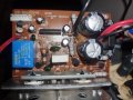
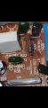
After removing amplifer I found resistor r34 burnt out.
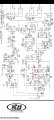
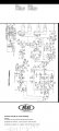
using schemic I found r33 resistor the same 22ohm so i used that to indentify the coloured lines of r34 and replaced with a 22ohm +-5 1W
New resistor burnt out instantly once powered on. I cant see any other damage on board except from a965 looks a bit black on the prong but not even sure what this component is?
Please help will be much appreciated. Thank you.
Screenshot_20240908_205815_Gallery.jpg20240908_205347.jpgScreenshot_20240908_204732_Adobe Acrobat.jpgScreenshot_20240908_204652_Adobe Acrobat.jpg
 

Attachments

Jean82

Joined Jun 12, 2023
28
Since R34 is the one, that burns out, I suppose, Q5 has C-E short. When I'm right, the current flows from GND through R38(5R6) - R34(22R) - Q5 - Q7B-E diode to the negative supply.
Q7 can also be shorted.
How do You check it with a voltmeter? In case it has a resistance meter function, then You can. Solder out Q5. You have to find a diode between B-E and between C-B. You must find an open circuit between C-E. A diode has low resistance when the meter connects a positive voltage at the anode and the negative at the cathode. Also, it has a high resistance when the polarity is reversed. In case of Q5, positive on emitter and negative on the base results a low resistance, reversed polarity results a high resistance. Positive on C and negative on B results low resistance, reversed polarity results a high resistance.
You can check Q7 with similar method, but, since it is NPN - in contrast with Q5 which is PNP - all the polarities are reverse.
Attention, the current through these semiconductors _should_ be low, in the 2-3 mA range, otherwise You can damage the component yourself. Don't try to check it for example with a battery and a lamp! A multimeter with resistor-measurement function will do. Multimeters usually have a diode-check function, it is also useful similarly. If You have a spare diode at hand, not in the circuit, You can try to check it first, and with this experience, You can check the transistors, too.
There may be other damage in the amplifier. Before burning out some other loudspeakers, I recommend to connect a high power 10-20R resistor in series with the loudspeaker and just then turn the amplifier on. When You hear some acceptable voice, just low volume, then the amplifier may work properly. When You don't hear anything or the voice is not what You expect, then there's another damage in the amplifier.
 

Thread Starter

simonn46988

Joined Sep 8, 2024
3
Since R34 is the one, that burns out, I suppose, Q5 has C-E short. When I'm right, the current flows from GND through R38(5R6) - R34(22R) - Q5 - Q7B-E diode to the negative supply.
Q7 can also be shorted.
How do You check it with a voltmeter? In case it has a resistance meter function, then You can. Solder out Q5. You have to find a diode between B-E and between C-B. You must find an open circuit between C-E. A diode has low resistance when the meter connects a positive voltage at the anode and the negative at the cathode. Also, it has a high resistance when the polarity is reversed. In case of Q5, positive on emitter and negative on the base results a low resistance, reversed polarity results a high resistance. Positive on C and negative on B results low resistance, reversed polarity results a high resistance.
You can check Q7 with similar method, but, since it is NPN - in contrast with Q5 which is PNP - all the polarities are reverse.
Attention, the current through these semiconductors _should_ be low, in the 2-3 mA range, otherwise You can damage the component yourself. Don't try to check it for example with a battery and a lamp! A multimeter with resistor-measurement function will do. Multimeters usually have a diode-check function, it is also useful similarly. If You have a spare diode at hand, not in the circuit, You can try to check it first, and with this experience, You can check the transistors, too.
There may be other damage in the amplifier. Before burning out some other loudspeakers, I recommend to connect a high power 10-20R resistor in series with the loudspeaker and just then turn the amplifier on. When You hear some acceptable voice, just low volume, then the amplifier may work properly. When You don't hear anything or the voice is not what You expect, then there's another damage in the amplifier.
Wow thank for your indepth response il try and find the short once im done work. Circuit board components arent all that expensive either so may just replace both emitters/collectors see what happens.
Thank you
 

sarahMCML

Joined May 11, 2019
695
Just to note: the resistor that you replaced was of a lower wattage than the original. Check the component list for the correct wattage value!
 

Jean82

Joined Jun 12, 2023
28
If You replace the components just to see what happens, the new ones may be damaged soon, just because there's still another failure somewhere in the circuit.
I recommend to find the failures first, analyse them and then replace all the damages ones.
 

Jean82

Joined Jun 12, 2023
28
> It may be a camera artifact, but the big electrolytic capacitors look to be bulging a bit at the top?

Well, it can be. When its top isn't flat, it's time to replace. When one has to be replaced, I would replace both.
 
Top