Replacing IC Differential Amplifier with IC OpAmp in a Current Source

Thread Starter

Carlos Martínez 1

Joined Nov 23, 2016
32
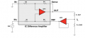
I want to make a Current Source with only Resistors, Capacitors, Inductances and Opamps(Not diodes or transistors) all biased by a Cell Phone Charger(5 VCC Supply) and get at least 2 mA. So I found the circuit attached, since I don't have any IC Differential Amplifier I tried replacing the gray squared part of the circuit(Differential IC) with a general purpose OpAmp and the same arragement of resistances, but in both Pspice Simulation as in breadboard the results were unfruitful, the current varied a lot with low Load Resistance changes. I have used and simulated: LM741, LF353, LM324 and TL082.

Any idea of a general Purpose OpAmp that I could use? Or a Differential OpAmp IC with all it's resistors matched?

Thanks.
 

Attachments

CEJones

Joined Feb 12, 2016
13
Why do you want to use op-amps and what sort of accuracy. You can easily make fairly reliable current source with two BJT transistors and two resistors.
 

ramancini8

Joined Jul 18, 2012
473
A purchased differential amp has matched resistors to gain differential accuracy. An op amp can function as a differential amp, but accuracy will depend on the resistors used.
 

dannyf

Joined Sep 13, 2015
2,197
this is a simple summing amplifier: the "differential amp" is really configured as a non-inverting amp and its operations don't rely on matching resistors.

it could be designed to utilize an instrumentation opamp. and if you could achieve the same with a typical opamp instead.
 

crutschow

Joined Mar 14, 2008
34,201
R_Out is a Trimmer 10k
R_Load Is a 1k Trimmer
All other resistors are from the same value 1k or 2k or 5k. Theorichally doesn't matter which is the value as they are the same
Theoretically it may not matter but practically it very much does. :eek:
You always have to be aware of the difference.
The load current has to go through R_out and a value of 10kΩ severely limits the output load current, depending upon the maximum output voltage of the difference amp.

Here is an LTspice simulation of your circuit (variation of a Howland current source) using a difference amplifier and an op amp, with the output load resistance varying from 500Ω to 2.5kΩ.
The output current is constant as the load resistance changes, indicating proper operation as a current source.

As ramancini8 noted, a differential amp has better matching of the resistors than can be readily achieved using an op amp with external resistors (would require 0.1% resistors to match the difference amp shown), and that matching determines the gain accuracy and the stiffness of the output current with change in load resistance..

upload_2016-12-28_12-4-1.png
 

Attachments

Last edited:

dannyf

Joined Sep 13, 2015
2,197
All other resistors are from the same value 1k or 2k or 5k.
how about power supply? dual rail / single rail? wiring? ...
opamp voltage-ccs.PNG
the above is your circuit. the blue trace is actually an overlap of 4 traces for Rload = 1k, 2k, 5k and 10k -> the fact that they are on top of each other shows you that the current output is invariant of the load.

you aren't helping yourself by not providing as much information and as early as you can.
 

Thread Starter

Carlos Martínez 1

Joined Nov 23, 2016
32
Theoretically it may not matter but practically it very much does. :eek:
You always have to be aware of the difference.
The load current has to go through R_out and a value of 10kΩ severely limits the output load current, depending upon the maximum output voltage of the difference amp.

Here is an LTspice simulation of your circuit (variation of a Howland current source) using a difference amplifier and an op amp, with the output load resistance varying from 500Ω to 2.5kΩ.
The output current is constant as the load resistance changes, indicating proper operation as a current source.

As ramancini8 noted, a differential amp has better matching of the resistors than can be readily achieved using an op amp with external resistors (would require 0.1% resistors to match the difference amp shown), and that matching determines the gain accuracy and the stiffness of the output current with change in load resistance..

View attachment 117620
I'll check that, and also will upload my simulation files, because using PSpice it doesn't works.
 

Thread Starter

Carlos Martínez 1

Joined Nov 23, 2016
32
how about power supply? dual rail / single rail? wiring? ...
View attachment 117624
the above is your circuit. the blue trace is actually an overlap of 4 traces for Rload = 1k, 2k, 5k and 10k -> the fact that they are on top of each other shows you that the current output is invariant of the load.

you aren't helping yourself by not providing as much information and as early as you can.

Sorry, here is what I've done so far: As you see, here is the circuit, all R are 1k, Ro 2k and RL is being varied from 0.1 to 1k, you can see that the current is also varying with the load. Theoretically the current should only depend of V1 and Ro, but it doesn't.

The equations I've got from solving the circuit:

IL=V1/Ro

Ro>RL

So, the only reason seems to be the OpAmp.
 

Attachments

crutschow

Joined Mar 14, 2008
34,201
Yup and it didn't worked, thats what concerns me.
What concerns me is that you persist in talking about theoretical calculations while ignoring the limitations of op amps in real circuits.
Those circuit values (and op amp voltages) in post #17 are certainly not what I used in my circuit.

Look in the op amp data sheet and design the circuit within its limitations.
Then your circuit will operate closer to the theoretical calculations.
 
Top