Facebook
 Google
 GitHub
 Linkedin
Hi E,hi C,
Retry post #68 program, you said it worked OK.
Thats using TMR1 interrupt.
E
Edit:
Compile program in post #74. post the hex file it creates, lets check your OSH.
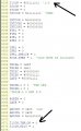
#68 works! I notice: T1CON = %00111101 '1:8
C.
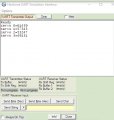
Attachments
-
2.5 KB Views: 1

")