Hi E,
Works a treat, thanks.
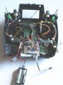
Just wiring the PCB into the transmitter for a 'live' test.
As radio control doesn't use '0' I'll move all of the POTs up one and get rid of the zero, I presume that's ok.
C.
Hi E,
While I can scan ASM, I can't understand it, but what I meant was like this:
''''''''''''''''''''''''''''''''''''''''''''''''''''''''''''''''''''''''''''''''''''''''''''''''''''''''''''''''''''''''''''''''
main:
Adcin 0, vpot1 'CH1
Adcin 1, vpot2 'CH2
Adcin 2, vpot3
Adcin 3, vpot4
Adcin 4, vpot5
Adcin 5, vpot6
Goto main
'''''''''''''''''''''''''''''''''''''''''''''''''''''''''''''''''''''''''''''''''''''''''''''''''''''''''''''''''''''''''''''''''''''''
This works, is it ok?
-------------------------------------------------------------------------------------------------------------------
As you can see I also tried adding Goto 'get_mess' This produced this error..
>>>>Hardware Stack Underflow.<<<<
C.
hi C,
When your code makes a GOSUB call it Pushes the Return Address onto a Stack,[ where it is saved] so when it completes the GOSUB and RETURN's it Pops that Return address off the Stack and the program execution continues from that Address.
If you use a GOTO command which ends in a RETURN, if the Stack is empty you get Hardware Stack Underflow, because a GOTO does not Push an Address onto the Stack.
If there was an 'old' Address on the Stack, this incorrect Return address would cause a program crash.
Hi E,
I've made a note of your explanation, thanks.
I've got 4x Channels working 'LIVE' I can switch on LEDs with the transmitter levers. Great!
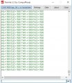
Next I'll try to transmit to a computer terminal (Termite or Teraterm) EDIT: I tried transmitting to a terminal, and it copies the channel readings ok, but then stops after a few seconds. Each time I switch the transmitter OFF/ON, it starts again then repeats the stop.
hi,
The only section with ############# is this bit.??
E
######################################
ADCON0 = %00000001 'BIT0 = 1A/D EN This Selects AN0 thru AN5 [ you have set for AN0]
ADCON1 = %00001001 'AN0-AN5 SET TO ANALOG IN Correct
ADCON2 = % 1 x 100 100 'Set for Right Justify, 8 Tad , Fosc/4
'#############################################
E,
So I assume they should be;
ADCON0 = %00001111 4x Till I make new 6x AN PCBs
ADCON1 = %00001001 'AN0-AN5 SET TO ANALOG IN Correct
ADCON2 = % 1 100 100 'Set for Right Justify, 8 Tad , Fosc/4 (Is this ok?)
hi C,
Look at the ADCON0 notes in the d/s.
You must enter all 8 Bits 0's or 1's to set up the ADC ADCON0 Byte correctly, [ bits 5 thru 2 select the channels] but the other bits also need to be set as required.
E
hi C,
Look at the ADCON0 notes in the d/s.
You must enter all 8 Bits 0's or 1's to set up the ADC ADCON0 Byte correctly, [ bits 5 thru 2 select the channels] but the other bits also need to be set as required.
E
Hi E,
I always check the D/S, but sometimes it's not clear.
Ok, another try:
ADCON0 =%00100?1 For 4CH
ADCON0 =%00110?1 Fro 6CH
I'm not sure about BIT1 EDIT: I've just seen that ADCON1 should be set for 4CH, so ADCON1 = %00001011
C.
Hi C,
Consider the bits 5 thru 2 of ADCON0 select the required channel.
You are programming for 6 channels, when you write the code below
The Oshonsoft Basic sets the correct ADC channel, prior to read from that channel.
This operation was shown in that demo program I posted, it read all the 6 channels OK.
Leave the ADCON0 as I set it.
E
 Facebook
 Google
 GitHub
 Linkedin