12VDC relays with 600 Ohm coils are common. The only thing we still don't know is voltage and current rating of the contacts. spec of the relay or device that is part of will reveal that.
12VDC relays with 600 Ohm coils are common. The only thing we still don't know is voltage and current rating of the contacts. spec of the relay or device that is part of will reveal that.
they are just showing a typical 600 ohm coil, DPDT relay, the contact ratings all depend on what you are connecting to them, if you are connecting a motor, it should have enough current capabilities to handle the motor current draw, if you are just using it as a contact closure type of device, then any low current relay contacts may be sufficient..... so to better answer your question, what are you planning on connecting to that circuit once you have built it?
That will work for the circuit as long as the load you are switching is less than 1 amp @ 125 VAC or 2 amps @ 24 VDC. So the question is... What are you turning on/off with the circuit?
they are just showing a typical 600 ohm coil, DPDT relay, the contact ratings all depend on what you are connecting to them, if you are connecting a motor, it should have enough current capabilities to handle the motor current draw, if you are just using it as a contact closure type of device, then any low current relay contacts may be sufficient..... so to better answer your question, what are you planning on connecting to that circuit once you have built it?
I am just trying to build that circuit, the PIR sensor will allow the LED to switch on when movement is detected.
It does not need to be connected to other things.
That will work for the circuit as long as the load you are switching is less than 1 amp @ 125 VAC or 2 amps @ 24 VDC. So the question is... What are you turning on/off with the circuit?
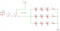
I see that there is an LED connected to one of the relay contacts. The other set of contacts, labeld "SW OUT", on the relay is intended to be connected to something you want to control. That portion is the determining factor to the load capacity of the relay. If all you want to do is build the circuit just for the learning process, then the relay you found on ebay will work fine for you. The "code" you see in the listing is just a model # and some info about the relay being sold.
I see that there is an LED connected to one of the relay contacts. The other set of contacts, labeld "SW OUT", on the relay is intended to be connected to something you want to control. That portion is the determining factor to the load capacity of the relay. If all you want to do is build the circuit just for the learning process, then the relay you found on ebay will work fine for you. The "code" you see in the listing is just a model # and some info about the relay being sold.
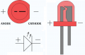
It is fairly simple to do that. Just connect your power supply positive for the LEDs to the relay, one of the SW OUT pins, then connect your LEDs anode to the other relay contact labeled SW OUT. Connect as many LEDs in parallel or series, your choice but dependent upon the voltage supply you are using. Connect the cathode of the LEDs to your current limiting resistor(s) then to ground.
Yes, though I do not know why you need to as the relay is essentially a switch.
It is fairly simple to do that. Just connect your power supply positive for the LEDs to the relay, one of the SW OUT pins, then connect your LEDs anode to the other relay contact labeled SW OUT. Connect as many LEDs in parallel or series, your choice but dependent upon the voltage supply you are using. Connect the cathode of the LEDs to your current limiting resistor(s) then to ground.
The pins you have labeled 1 & 8 are the coil. It doesn't matter which is positive and negative as long as the protection diode goes in like on your first schematic. Pins 2, 3, & 4 are one set of relay contacts. Pins 5, 6, &7 are the second set of contacts.
The schematic of the relay is just an easy to use representation of the internal components of the relay. It does not necessarily mean that is how the pins actually are.
Do not get hung up on the pin numbers. You will find that when you order the relay you need or if you look at a datasheet of a relay, the pin numbers are really different than what you think they are.
Just look at the contacts as NO - C - NC, which is Normally Open - Common - Normally Closed. If you can identify them that way you will be in better shape.
 Facebook
 Google
 GitHub
 Linkedin