 Facebook
 Google
 GitHub
 Linkedin
Hi Everyone,
New member here—joined today!
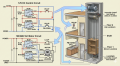
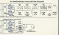
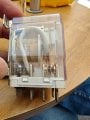
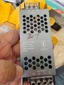
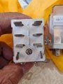
I've built a 2-stop dumbwaiter running from basement kitchen to ground level kitchen. Thought the logic controller would be simple, so I used AI for help. Got 2 circuit diagrams based on 2x 12V 30A DPDT relays—I've got all the hardware ready, but the diagrams totally confuse me.
Can someone please:
Thanks in advance!
Best regards,
Ajeet
New member here—joined today!
I've built a 2-stop dumbwaiter running from basement kitchen to ground level kitchen. Thought the logic controller would be simple, so I used AI for help. Got 2 circuit diagrams based on 2x 12V 30A DPDT relays—I've got all the hardware ready, but the diagrams totally confuse me.
Can someone please:
- Explain how these circuits work (or what's wrong with them)?
- Or better yet—provide a clearer, simpler alternative?
Thanks in advance!
Best regards,
Ajeet
Attachments
-
 1.6 MB Views: 40
 -
 147.2 KB Views: 39
 -
 186 KB Views: 34
 -
 219.4 KB Views: 26
 -
 170.7 KB Views: 24


