Facebook
 Google
 GitHub
 Linkedin
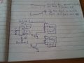
So I am fabricating a dumbwaiter and I need a control system. I am using a 200kg winch to power the lift. The winch comes with an upper limit switch and a wired up/down/stop controller.
I will need to install 2 lower limit switches and 1 additional upper limit switch. I purchased 2 wall mountable push button switches that have up/down/stop buttons and I also got some magnetic switches to stop the motor in case the shaft doors are open.
I need to wire the push button switches so that if a person upstairs is pushing the up button and someone downstairs is pushing the down button only one will work at a time.
The motor is very slow and the travel distance is only about 3 meters (counter height 1st floor to counter height 2nd floor). The lift will only be used for plates of food and not for sacks of flour so I don't need an overweight sensor.
Should I go with an arduino or should I go with relay logic? I am a home electrician so I have no problem working with 220v single and 3 phase. I am not skilled with circuits and small electronics but I have made some very basic kit circuits recently and this is a great opportunity for me to learn more. Could anyone provide me with a diagram on how this could be done?
Much Thanks