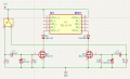
Anything (not so) obviously wrong with this latching relay toggle?

Thread Starter

Schluppy

Joined Jun 7, 2024
33
20260712.relay_toggle.001.png

The purpose is to maintain state between power cycles -- so it's sort of a power-on reset -- and permit state changes during normal operation.

The basic design was taken from a previous thread where you all helped me figure out how to drive multiple relays from a CD4013.

The differences here being:

A. We're driving the relay with a physical toggle switch rather than a flip-flop

B. the Schottkys (D1, D4) which suppress the negative voltage spike that occurs when the voltage is abruptly removed, and;

C. the resistors (R1, R4) that pull down the differentiator caps when the voltage is abruptly removed.

So, in addition to feedback regarding the general viability of the circuit, I'd also appreciate some advice for selecting correct values for the same two components; the Schottkys and the pull-down resistors. I selected BAT42 & 1k primarily because they were already on the bench (and they work) but perhaps there are some better choices to be made.

Thanks!
 

crutschow

Joined Mar 14, 2008
38,589
B. the Schottkys (D1, D4) which suppress the negative voltage spike that occurs when the voltage is abruptly removed
Don't need those diodes.
Any negative spike generated by removing the voltage will not damage the MOSFETs.

And diodes D2 and D3 do nothing.
If you want to suppress the relay coil inductive spike (which you should) then connect the diodes directly across the coils, cathodes to +5V.
 

Thread Starter

Schluppy

Joined Jun 7, 2024
33
Don't need those diodes.
Any negative spike generated by removing the voltage will not damage the MOSFETs.
Is that universally true whenever you have a differentiator feeding the gate of a MOSFET?

And diodes D2 and D3 do nothing.
If you want to suppress the relay coil inductive spike (which you should) then connect the diodes directly across the coils, cathodes to +5V.
They're recommended by the manufacturer. There was a brief discussion about it in the previous thread that I linked above.
 

crutschow

Joined Mar 14, 2008
38,589
Is that universally true whenever you have a differentiator feeding the gate of a MOSFET?
Yes. The gate max voltage rating is for plus and minus voltages, so if it can tolerate the plus voltage, it can also tolerate a similar value minus voltage.
They're recommended by the manufacturer.
Yes, but that's for the connection of two different relay coils in parallel and you only have one relay.
You need to suppress the voltage spike at the MOSFET drain, as the voltage spike will be positive from the bottom of the relay coil to the MOSFET drain, which can zap the MOSFET, and the diodes you show have no effect on that.
 

Thread Starter

Schluppy

Joined Jun 7, 2024
33
Alright, so...

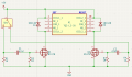
A single relay, just the diodes parallel to the coils to suppress the back EMF:

20260712.relay_toggle.002.png


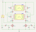
And, for multiple relays, the diodes parallel to the coils to suppress the back EMF and diodes to suppress induced currents in the opposite coil:

20260712.relay_toggle.paralell.001.png

Am I interpreting your advice correctly?
 
Top