Relay switcing causing brown out of ESP32

Thread Starter

sirch2

Joined Jan 21, 2013
1,075
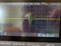
Transient.jpg

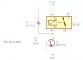
I am driving a couple of relays from an ESP32, some combination of switching the two relays gives the above tranisent on the ESP32 power lines which is enough to cause a brown-out. The whole thing is driven from an ~18v battery (or bench PSU) with buck converters to give 12v for the relays and 3.3v for the ESP. The relays have flyback diodes and 100uF capacitors across them and are switched from the ESP by low-side BJTs. I've tried a range of capacitors on the input to the ESP including things like 220uF electrolytic plus a 100nF ceramic, etc but this keeps happening.

Switching one or other relay independently is okay but some combination of switching them both close together, there is always about 200mS delay between switching them off causes this. it was all working fine on the bench but when I got it into the enclosure this started happening and now it happens on the bench too. Any ideas as to how I suppress this?
 

panic mode

Joined Oct 10, 2011
5,233
schematics? pictures? what kind of enclosure? if it worked on the bench but not inside enclosure, my first suspicion is that it is a metal enclosure and mounting board there introduced ground loops, which did not exist when board was on the bench. and please crop/resize images in your posts. 1200 pixel horizontal is plenty...
 

B-JoJo-S

Joined Jan 3, 2026
516
Out of my comfort zone here - but a relay coil is basically a coil; and a capacitor in combination forms a tank circuit. Your trace looks like a tank circuit. Have you tried switching them without the cap? You're correct in using a flyback diode, so don't remove that.

Alternatives: Can you use a MOSFET to do the switching instead of the relay?

Questions: Exactly how is the cap on the relay? Across the coil? In series with the coil (which shouldn't work if the relay is DC powered)
Are you switching an AC source?
Is your relay contacts SPDT or DPDT (or 3P or more / DT)?

EDIT: See https://www.allaboutcircuits.com/te...rrent/chpt-6/parallel-tank-circuit-resonance/
END EDIT.
 

Thread Starter

sirch2

Joined Jan 21, 2013
1,075
Out of my comfort zone here - but a relay coil is basically a coil; and a capacitor in combination forms a tank circuit. Your trace looks like a tank circuit. Have you tried switching them without the cap? You're correct in using a flyback diode, so don't remove that.
Good call regarding the tank circuit, initially I didn't have the caps but I was getting a different brown out issue, its been through several iterations so perhaps no caps on the relays but more/different on the ESP power lines might work
 

Reloadron

Joined Jan 15, 2015
7,937
While I am unsure of your exact relay config I have had no problems using relay boards single channel up to 16 channel relay boards similar to these. This includes ESP 32, ESP 8266 and other assorted uC projects. They all work just fine. If all else fails I would give a relay board a shot. Newer boards like I linked to include I2C communication.

Ron
 

panic mode

Joined Oct 10, 2011
5,233
same here... properly used relays are not a problem. to determine problem we need to see entire circuit and construction. also it would be nice to get confirmation if bench tests included loads. maybe problem is not the control side, it is the load side.... also how is the ESP power derived/maintained? any caps to filter out glitches here?
 

MisterBill2

Joined Jan 23, 2018
28,223
First question: WHAT is the purpose of the capacitors across the relay coils?? I see no possible benefit from that, only a greatly increased inrush current for the control device. A capacitor across the power source could make sense, but not across the relay coil. The diode across the coil will clamp the flyback pulse AND ALSO slow the drop-out of the relay a small amount.

Now, I have another though! How much current does the relay coil require?? What is the specified maximum output current from the power supply for thatprocessor board?? Is the power supply connection to the processor module adequate to carry the total current without an excess voltage drop??
What the scope trace looks like to me is that a power supply overload is happening.
 
Last edited:
Hello, from experience I rarely drive relays with an ESP32 (or some other microcontroller) directly without some form of buffer (or maybe circuit that slows down the signal slew rate that activates the relays)
i.e. microcontroller (ESP32) => demux => buffers => relays as I've designed automation systems with lots of relays (and even with this consideration in mind I still get problems with relay bounce from time to time)
(There's also a need to ensure each relay is driven with enough current from the buffer)

Hope this helps somehow.
Cheers,
Justin
 
Certainly driving a transistor to control the relay is a better choice, unless the required relay coil currents are within the specified capability of ESP32 you are using. BUT using an external transistor as the driver is a good choice, although certainly it is much less convenient. Adding a buffer stage should also provide some protection against the inductance effects on the voltage and current, and added currents that are not so obvious, in other portions of the current loop.
 

wraujr

Joined Jun 28, 2022
265
Using disgram in Post #4, any large caps should be connected to pin 1 of the relay and to GND to provide surge current during relay switch. Absolutely no caps across relay coil or at switching transistor.
Next, you are showing 3.3V supply and current surge would be on +12V supply. Without sufficient bulk capacitance on the output of the +12V supply your current surge would work its way back to the 18V supply and cause voltage brownout at 18V thereby affecting 3.3V supply.
That said the scope trace does not show a voltage droop as much as possibly ground bounce. You need to pay attention to your grounding especially if this is a bunch of loose wires or proto board. Try creating two sepearte GND distributions, +3.3V and +12V and the tie these two GNDs together, preferably at the output of both buck regulators.
 
The one place where a capacitor across a relay coil works is when the DC coil relay is driven by a diode rectified AC signal, such as the output of an audio amplifier. There is almost never any other GOOD reason for a capacitor across a relay coil.
ALWAYS, a capacitor across the relay coil adds to the current surge when DC is applied to operate the relay, if the coil voltage is being switched on and off.
The reason is that the capacitor usually slows both the closing and the opening of the contacts, which tends to encourage arcing, if there is much power involved. And even with low-level signals, slow operation encourages contact bounce.
 
Last edited:
It looks to me that you are supplying the 3.3v to the esp 32 from a switch mode supply. Its not well designed ( loop damping is msrginal) and so oscillates on step load. The datasheet for the esp32 says use a well regulated supply, which is usually taken to be a linear regulator. Try that for the esp32 supply.
 
Questions!! How much current is the relay specified to draw at the voltage you are using?? What is the specified maximum current of the ESP device claimed to be?? AND, how much current is the power supply for the ESP rated to deliver??
It is quite possible to overload a power supply and get un-anticipated results.
 

Reloadron

Joined Jan 15, 2015
7,937
What is the specified maximum current of the ESP device claimed to be??
Best case any DIO pin on the ESP32 can deliver 20 mA (0.020 amp). The max voltage on any DIO pin will be 3.3 volts.

I have yet to see an accurate schematic from the thread starter. They mention using a 12 volt relay and a transistor driver but that's as good as it gets.

Ron
 
Top