Relay circuit help for a pump in my car

Thread Starter

merzatt

Joined Jan 15, 2009
43
Hello forum members,
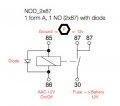
I would like to add a relay circuit to my car for auxiliary coolant pump. Currently pump is controlled by the AC control unit (AAC) without a relay. This pump known to seize and sometimes burns the circuit board of the AAC which is expensive. I would like to use the AAC as the signal to the relay and feed the pump from the battery nearby. I was told to place a protective (freewheeling) diode as well so that when the AAC stops the pump, there won't be a surge from the relay coil (I am a newbie and not sure what I am talking about here..)

Please comment about my circuit below. Is the diode placed correctly? 14 V is the battery supply. Since this pump runs when the engine is running, voltage is approx 14 V due to charging. Can this extra 2V harm the pump? Pump also runs for 5 mins after the engine is off and at that time battery voltage is 12v.

12 V on the left side is going to be my signal from the AC control unit.

http://lushprojects.com/circuitjs/circuitjs.html?cct=$+1+0.000005+10.200277308269968+50+5+50 178+544+320+688+320+0+1+0.2+0+0.05+1000000+0.02+20 g+384+432+384+448+0 R+544+320+544+256+0+0+40+14+0+0+0.5 r+544+368+544+432+0+500 w+768+240+768+336+0 g+608+240+608+256+0 181+688+336+768+336+0+1840.5922678055792+30+12+0.4+0.4 w+512+432+544+432+0 w+512+352+544+352+0 w+608+240+768+240+0 w+384+432+512+432+0 w+480+352+512+352+0 s+320+352+384+352+0+1+false R+320+352+320+432+0+0+40+12+0+0+0.5 d+384+352+480+352+1+0.805904783

RelayCtrl_merzatt_01.gif

RelayCtrl_merzatt_02.gif
 

shortbus

Joined Sep 30, 2009
10,045
No your diode isn't in correct position. The diode goes in parrallel with the coil of the relay. To make life simpler for yourself, why not use one of the automotive relays with an internal diode? They do make such an animal. First link I found to one - http://www.altecautomotive.co.uk/5-...elay-with-diode-protection-altry18-2542-p.asp

Here's a link on automotive relays that explains the different types and how to choose them - http://www.12voltplanet.co.uk/relay-guide.html

To answer the 12V/14V question, even though they are called 12V circuits in a car, the ~14V is the real voltage when the engine is running. Don't worry about it. :)
 

Thread Starter

merzatt

Joined Jan 15, 2009
43
No your diode isn't in correct position. The diode goes in parrallel with the coil of the relay. To make life simpler for yourself, why not use one of the automotive relays with an internal diode? They do make such an animal. First link I found to one - http://www.altecautomotive.co.uk/5-...elay-with-diode-protection-altry18-2542-p.asp

Here's a link on automotive relays that explains the different types and how to choose them - http://www.12voltplanet.co.uk/relay-guide.html

To answer the 12V/14V question, even though they are called 12V circuits in a car, the ~14V is the real voltage when the engine is running. Don't worry about it. :)
Thank you shortbus. Did some search and found TYCO single pole single throw horn relay, 1 form A, NOD (2x87). 12V, 30A inductive load with diode. available in the US.
Tyco Mini Relay 12V SPST 40A V23234C1001X008 Waytek site

I will install a 10 amps fuse between this relay and the battery.

Terminal 85 -> [? resistor] -> AAC ground
Terminal 86 -> AAC 14V (turn on signal)
Terminal 30 -> [10 amp fuse] -> battery 14v
Terminal 87 -> Pump
Terminal 87 -> empty

Is it necessary to install a resistor between 85 and ground?
It has two terminal 87. Can I install an LED to the second terminal, so I will have a visual indicator when it is running.
 

shortbus

Joined Sep 30, 2009
10,045
Not sure what your asking? Can you make a drawing/schematic of how you think it should be wired.

The two terminal 87 (A and B) are not the same, one is N/O (normally off) the other is N/C (normally closed or on). The N/C contact is 'on' when there is no power to terminal 85 or 86. If you want an LED to be on when pump is on, wire it to the same terminal as the pump. Again to save a hassle get a LED automotive indicator, they have a built in voltage resistor an a snap in housing/bezel around the LED. Just need to drill a hole and pop it in and connect. If you use a regular LED, you need to add a resistor and make some kind of bezel or holder for it. Just one of the many links for them - http://www.partdeal.com/red-led-indicator-light-12-24v-dc-8171-blue-sea-systems.html?zmam=74973193&zmas=1&zmac=4&zmap=77122764&gclid=CJC5mM_RtswCFYsCaQodm9oLsQ .

Terminals 85 and 86 are the pull in coil terminals, they can be used interchangeably, one to ground and the other to the switch. No resistor needed.

Terminal 30 goes to the power/fuse.

Hope this helps you.
 
Last edited:

Thread Starter

merzatt

Joined Jan 15, 2009
43
Not sure what your asking? Can you make a drawing/schematic of how you think it should be wired.

The two terminal 87 (A and B) are not the same, one is N/O (normally off) the other is N/C (normally closed or on). The N/C contact is 'on' when there is no power to terminal 85 or 86. If you want an LED to be on when pump is on, wire it to the same terminal as the pump. Again to save a hassle get a LED automotive indicator, they have a built in voltage resistor an a snap in housing/bezel around the LED. Just need to drill a hole and pop it in and connect. If you use a regular LED, you need to add a resistor and make some kind of bezel or holder for it. Just one of the many links for them - http://www.partdeal.com/red-led-indicator-light-12-24v-dc-8171-blue-sea-systems.html?zmam=74973193&zmas=1&zmac=4&zmap=77122764&gclid=CJC5mM_RtswCFYsCaQodm9oLsQ .

Terminals 85 and 86 are the pull in coil terminals, they can be used interchangeably, one to ground and the other to the switch. No resistor needed.

Terminal 30 goes to the power/fuse.

Hope this helps you.
Sorry, I should have inserted the diagram. Here is the relay connections. No resistor, no LED. P=pump. How does it look?
 

Attachments

Thread Starter

merzatt

Joined Jan 15, 2009
43
Guys,
I checked the HID relay which is controlled by another computer in the car. It has a LED and resistor inside. Since LED is cousin of diodes, do you think will it function as a protective (freewheeling) diode as well? Or should I add an external diode?

Thanks
 
Top