hmm interesting am i close to correct in thinking this is overlaying two consecutive square waves to control duty cycle?
i thought about that previously.
hey thanks greatly for this - and for taking the time to share - i don't presently have LTspice but am sure i can acquire it.
thanks for the higher res image - i'll look it over to see what else i can learn here.
hmm interesting am i close to correct in thinking this is overlaying two consecutive square waves to control duty cycle?
i thought about that previously.
No, sorry...
What happens is that the AC out of the 24 volt winding is full-wave rectified, attenuated by the voltage divider R1R2, and sent to U1, a voltage comparator used as a zero-crossing detector. U1 produces a short, low-going pulse, ZC-, which straddles the low-going peaks of the full-wave rectified AC waveform, ZCAC.
ZC- is used to trigger U2, a 555 one-shot which generates a positive pulse with a period corresponding to
t = 1.1R7C3.
When U2 times out it generates a negative edge which is differentiated by C3 and used to trigger U3. U3 is used to generate a short positive pulse which is used to latch the RS latch U4B U4C,and turn on M1 for the remainder of the DC half-cycle in play at that time, and when the half-cycle decays to zero volts, U4A will reset the latch and turn M1 OFF.
Note that the longer U2 stays ON, the shorter will be the time 33DC will be allowed to pump current through R10. That is, the shorter the output pulse from U2, the more power R10 (your soldering iron) will dissipate. Also note the signal into R10 is full-wave rectified AC and the power dissipated by M1 will be much less than that dissipated by a TRIAC.
I've not shown it, but R7 might best be replaced by a pot sufficiently padded to make sure that U2's output pulse is always shorter than 10 milliseconds if the AC mains are 50Hz.
Zoom in on a cycle or two of the plot and you can easily see the sequential nature of the machine.
indeed it looks like a step up in functionality from the dimmer switch but also simple enough to be reliable - in keeping with your tag i guess : )
I have learned a lot while doing this - so far:
- Zener diodes (basic functionality) - and how they effect the knee curve on a pulse.
- about inverting a signal
- many others 'basic' things.
BTW that funky signal was as a result of my nasty bench PSU - i have now a clean pulse and am just learning about the 'inversion' process.
as i left out the opto going to the base trigger for the NPN.
i'll send some shots of where i am in the process.
well it appears i do have an inverted voltage here at the zero cross - (which is an achievement for me so far)
i'm trying to learn the aspects of voltage inversion in this simple case.
although the results don't represent the AN3006 per say, however i did skip the opto on the side going to the gate.
I just (as stated) created two bridges - and ran one though a set of 'caps' and a 'inductive' choke so that is what is ultimately being passed though the NPN 'magnetic' switch.
this make me wonder about the obvious question, you could invert voltage with inductors also right? (i haven't looked into yet)
Capacitors together with inductors are termed filters and generally form a filter of some kind and can effect a phase shift, depending on how they are used, (see LC tuned circuits) one of the simplest way to invert a signal without loss is generally a Mosfet, transistor or logic IC.
Max.
Capacitors together with inductors are termed filters and generally form a filter of some kind and can effect a phase shift, depending on how they are used, (see LC tuned circuits) one of the simplest way to invert a signal without loss is generally a Mosfet, transistor or logic IC.
Max.
this is a good simple video that helped - i just have to translate it into the words i use ha ha.
now i just have to figure out why i'm blowing up the transistor (once i connect it to pin 2) - but i don't think that will be insurmountable it can only be so many variables.
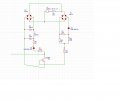
Here is the circuit so far this doesn't include the 555 but it is only when i connect the inverted section to Pin 2 does the Trans overheat and fry.
it seems maybe as it triggers to the separate load it is shorting?
ah because with the opto the gate gets sent to GRD when the opto switches on and when it is off it is sent to GRD though the Trans.
but in my setup the gate is not sent to GRD.
maybe instead of adding the R i should just ground the Gate back to before R9 ? (in the image) i.e back to GRD on that side?
in which case strange that it was working at all ? but i got (and continue to get those readings) all be it now that the Trans got fried they are a bit more messy (but that's fine i can find lots of these NPN)
because one rectified source is smoothed DC and the other is the rectified to give the 'zero crossing' ref.
I planned on running the 555 from the smoothed VDC and gain the zero cross ref from the non-smoothed rectified point
(and i got these signals [linked previously} with no load on the so called 'pull up' resistor)
if i just use one rectifier i only will have smoothed VDC, then i have to get the zero cross ref from somewhere.
The AN3006 uses the 115VAC for the Zero cross ref by passing it though the opto - but just says that the opto and the 555 are driven by :
"using a variable pulse width generated
from an optically isolated logic system with a control voltage
of 5 to 15 VDC "
the schematic doesn't provide any source for the 'Vcc'
but indeed the actual pulse and the gate have a common ref i.e they are driven by the same Vcc - where as that design i had there the gate was not GND where as in the AN3006 the signal goes though pin 4 of the H11L1 and to GND, so i guess that's the issue, maybe....
The Vcc is presumed to be designer/customer supplied from an individual source, this makes the logic circuit isolated.
If you use this method the input and output have to be isolated.
In my case I power the 5v logic for the micro from the same source as the bridge.
Max.
The Vcc is presumed to be designer/customer supplied from an individual source, this makes the logic circuit isolated.
If you use this method the input and output have to be isolated.
In my case I power the 5v logic for the micro from the same source as the bridge.
Max.
The Vcc is presumed to be designer/customer supplied from an individual source, this makes the logic circuit isolated.
If you use this method the input and output have to be isolated.
In my case I power the 5v logic for the micro from the same source as the bridge.
Max.
lets say i'm just using a 9v battery to run the 555, then the problem becomes where and how to get the pulse to switch on the zero cross. which is why any of it functions by controlling the 'phase cut 'of the AC though the duty cycle of the 555.
in my case i have a Transformer with two outputs (one that will run the iron) so i need something to run the 555 (and also a zero cross ref)
I might just run it off the 240v with an opto as that then simplifies the 555 (or indeed off the 24v with an opto which hey makes more sense i guess)
No, if you look at the circuit I posted earlier the only opto is the Triac driver, not the detection. I am using a 5v zener to regulate the Pic supply.
I am detecting the 720us pulse before the zener.
If you use a 9v battery for the logic then it would be advised to use the set up as in the AN 3006.
Max.
ok you are talking about 'D4' in your image? - I can't see much else on there the Res is too low but that helps, for example on my DL image it looks like there are 2 D4's.
no i won't use a 9v battery but i will need a zero cross ref.
 Facebook
 Google
 GitHub
 Linkedin