Facebook
 Google
 GitHub
 Linkedin
MaxHeadRoom
- Joined Jul 18, 2013
- 30,674
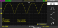
I don't know why you are getting that signal in 3rd png?
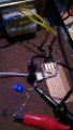
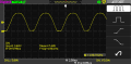
I ended up using the circuit I showed earlier, but I did assemble the version in the AN3006 fig3 and scoped it and got the clean pulse as shown in Fig 4. also at the output of the H11L1.
Max.
I ended up using the circuit I showed earlier, but I did assemble the version in the AN3006 fig3 and scoped it and got the clean pulse as shown in Fig 4. also at the output of the H11L1.
Max.