Question regarding triggering a Triac with a 555

Thread Starter

K.e

Joined May 7, 2017
81
hello I'm learning about 'electronics'

I have a dual step down transformer - 240v to 24~ and 10~ v out

- I full wave rectified the 10v out and ran it though a 555 to create a rough duty cycle controlled freq.

- now I want to attach the Triac to the 24v~ out (same trans) and trigger it with the 555.

The aim here is two fold, to learn the basics of what humans are calling 'electronics' also to create a variable resistance for a soldier Iron, I'm fully aware (now) that i could have just used a so called 'dimer switch' which is apparently a Triac and associated Cap and inductor choke.

however i'm more interested in variable pulse systems as i intend to use them in resonance circuits later.

(sorry for the story)

summary:

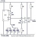
so i have a (dirty) duty cycle adjustable frequency out of the 555 (similar to this circuit) :

http://www.electroschematics.com/wp-content/uploads/2010/07/pulse-generator.gif (also see attached)

( just used a fixed capacitor for the primary freq selector so no rotary switch)

what is the results of the action of just hooking the output directly to the base of the Triac? i'm asking directly, i mean with no 'resistors' then the 24v to the end of the solder Iron using the Triac as the magnetic switch it is.

if i adjust the duty cycle of the 555 circuit it should also adjust the on time for the triac?

i have trouble understanding 'volts' and 'resistors' (and associated relationships)

(i'm not interested in any temp output reading from the Iron as i'll use common sense to know if the solder iron is hot enough or not)

i have some Moc20~ octo-c but the result from the 555 circuit give me 4.5~ 'volts' to 0~ volts as i adjust duty cycle so ??

thanks for any feedback.
 

Attachments

Thread Starter

K.e

Joined May 7, 2017
81
sorry for the confusion the 555 circuit i used is the image attached not the linked image - the used circurt uses a comparator and does not utilize the 'output' pin. (can't edit due to 10 min limit)
 

AlbertHall

Joined Jun 4, 2014
12,625
You have a triac in series with the AC supply to the soldering iron heater. When the triac is triggered it will begin to conduct and it will continue to conduct until the end of the AC supply half cycle. The '555 circuit can trigger the triac but it cannot turn it off again.

If the frequency of the '555 is higher than the AC supply then the triac will be switched on most of the time and the duty cycle of the '555 will have very little effect. However, if the '555 frequency is a good bit lower than the AC frequency, then the conduction of the triac will roughly follow the output of the '555. The soldering iron heater will have a fairly slow heating and cooling cycle so, being on for half a second and off for half a second will give half power and a steady temperature of the iron. So set the '555 frequency to something like 1Hz and this will work.
 

Thread Starter

K.e

Joined May 7, 2017
81
You have a triac in series with the AC supply to the soldering iron heater. When the triac is triggered it will begin to conduct and it will continue to conduct until the end of the AC supply half cycle. The '555 circuit can trigger the triac but it cannot turn it off again.

If the frequency of the '555 is higher than the AC supply then the triac will be switched on most of the time and the duty cycle of the '555 will have very little effect. However, if the '555 frequency is a good bit lower than the AC frequency, then the conduction of the triac will roughly follow the output of the '555. The soldering iron heater will have a fairly slow heating and cooling cycle so, being on for half a second and off for half a second will give half power and a steady temperature of the iron. So set the '555 frequency to something like 1Hz and this will work.
thank you for the reply -

ok so the Triac is set to switch off every 'half cycle' i.e after a full 'ac' pulse. then must be triggered again, i see thank you this info helps greatly.
and that's why at >50hz~ it will be dependent on the 'phase' cycle and switched on most of the time (unless perhaps timed at a harmonic multiple of the 50hz~ which would be probably not very accurate) i guess that's part of the purpose / existence of so called 'zero crossing' triggers?

thank you, you have saved me time and i have learned here.
 

Thread Starter

K.e

Joined May 7, 2017
81
You have a triac in series with the AC supply to the soldering iron heater. When the triac is triggered it will begin to conduct and it will continue to conduct until the end of the AC supply half cycle. The '555 circuit can trigger the triac but it cannot turn it off again...........

.
Thinking more about it and with the new info you have helped me with, maybe i should use a more 'traditional' 555 signal and try to accurately adjust it from 1hz~ to 50 - 60hz~ and leave alone the duty cycle for this particular application.
 

Thread Starter

K.e

Joined May 7, 2017
81
ah ok thank you, in my right now brief experience i have started to discover that. thanks. the fun continues....
 

Thread Starter

K.e

Joined May 7, 2017
81
As your application uses a transformer to power both the load and the '555 you don't need to bother with the optical isolation.
ah indeed thank you on the rectified side it was self evident , however less self evident on the load side in this diagram, thanks for clearing it up i see the Traic is the zero crossing trigger.

so the gate would be driven directly by pin 3 on the 555, so it appears the 'magic' here is the MPSA40?, i guess i should keep reading.
 

Thread Starter

K.e

Joined May 7, 2017
81
thanks for this, this looks like a fun and interesting circuit that might just actually also do what i want it to do.
 

MaxHeadRoom

Joined Jul 18, 2013
30,661
ha i was about to say "what's the purpose of MPSA40 ?"

but all i had to do was read, thanks for the lead.
The MPSA40 is because the 555 requires a negative going pulse, I used a Pic micro instead of the 555 as I needed more features, in this case the inversion is not necessary and the output of the H11L1 directly inputs to the pic.
Max.
 

Thread Starter

K.e

Joined May 7, 2017
81
The MPSA40 is because the 555 requires a negative going pulse, I used a Pic micro instead of the 555 as I needed more features, in this case the inversion is not necessary and the output of the H11L1 directly inputs to the pic.
Max.
hmm interesting yes so i guess really the 'zero crossing' sync is the 'magic' in this case as the whole system is frequency synchronized to the EM vortex and In my case though the same transformer, allowing for the Triac gate to function in an adjustable fashion.

as opposed to say for example running a 555 or something more advanced (your case) from a different sourced DC imbalance.
 

MaxHeadRoom

Joined Jul 18, 2013
30,661
hmm interesting yes so i guess really the 'zero crossing' sync is the 'magic' in this case as the whole system is frequency synchronized to the EM vortex and In my case though the same transformer, allowing for the Triac gate to function in an adjustable fashion.

as opposed to say for example running a 555 or something more advanced (your case) from a different sourced DC imbalance.
In order to implement the phase angle control for same point in each cycle the same trigger (crossover point) has to be known.
Max.
 
Last edited:
Top