question for the seasoned

Alec_t

Joined Sep 17, 2013
15,120
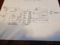
Yes. As I said in post #213,
"In the Test position only, S1b connects the cathodes of diodes D1,D2 to ground. This allows base current to flow in both Q1 and Q2 via R4 and R6, thus switching on Q1 and Q2 irrespective of the state of both the dark sensor and the PIR."
 

Thread Starter

fredric58

Joined Nov 28, 2014
252
yes you did, my apologies. I went to look for the post to answer your question about the clock and I must have gotten side tracked. which is good in a way because it made me have to look at it very closely to determine how it works. and the light did come on!!!

in regards to the clock. would it require (4) individual clock circuits if I wanted to change the wait time between the 10 second pulse. like have (4) settings, 15 min, 30 min, 45, and the original hour?
 

Thread Starter

fredric58

Joined Nov 28, 2014
252
OK, I am going to "attempt" to use the software to lay this out. I am fairly SURE that I will need to change the component numbers on the clock circuit because it will/would be confusing to the program to have (2) C1, (2) R1,234 etc???? correct?
 

Alec_t

Joined Sep 17, 2013
15,120
in regards to the clock. would it require (4) individual clock circuits if I wanted to change the wait time between the 10 second pulse. like have (4) settings, 15 min, 30 min, 45, and the original hour?
No. The wait time is determined by which of the 4060's outputs are logically combined by AND gate U1b. At present we are using outputs q9, q10, q13 of the 4060 but you could use a 3-pole multi-way switch to select those or other outputs. (N.b the 4060 doesn't have a q11 output).
I am fairly SURE that I will need to change the component numbers on the clock circuit because it will/would be confusing
You're right. If you can post a pic of the circuit with the new numbering then we'll be singing from the same hymn sheet to avoid further confusion :).
 
Last edited:

Alec_t

Joined Sep 17, 2013
15,120
Ok. And here's how you could modify the 'clock' by using a 3P3T switch to select times of ~ 24 min, 30 min and 57 min.
Timer4060Mod.gif
 

Thread Starter

fredric58

Joined Nov 28, 2014
252
OUCH!!!! that makes my head spin.....but...every problem has a solution, right? OK... the way I constructed the timer circuit, or I should say, the way I used the pins from the 4060 TO the 4073B is as follows. this is from the original design. for U1a I used pins 11, 12 and 13. U1b I used pins 3, 4 and 5. U1c I used pins 1, 2 and 8. my understanding is I can use each group (of3) because they ALL operate the same? AND that I could choose which ever combination I want to facilitate simplest the wiring path. (because for now I am using a single sided copper clad board.

my point being "before" I make a mistake, electronics are NOT FORGIVING. I can use any group, BUT, if your initial pin selection was different from mine our results "may not" be the same????? so I am thinking, "what if Alec chose 1,2, and 8 for U1a??? instead of my choice of 11, 12 and 13.

is that a legitimate question???
 

Alec_t

Joined Sep 17, 2013
15,120
I didn't show any specific pin numbers for the 4073B connections. The mod can use the same (correct) pins you are now using, as described above.
Just to confirm: the 4073B contains 3 equivalent AND gates, each gate having a set of 3 equivalent inputs.
 

Thread Starter

fredric58

Joined Nov 28, 2014
252
i remember my dad telling me to "keep it simple" don't over think it, and a bunch of other stuff I wish he was still here to talk about. 30 minutes. just 30, nothing else. it's close enough to 20 and close enough to 45. and it will take half the time to test to see if it works. how do I do that? I understand it better when I build it. actually.... I understand it better when I build it, they FRY it, and then figure out WHY! it's not frustrating anymore, it's just fun and fascinating! I wish I would have started when I was 5.
 

Alec_t

Joined Sep 17, 2013
15,120
The Q outputs of the 4060 go high ~N minutes after the 4060 gets reset, according to the following:-
Q........N
Q9.....3
Q10...6
Q12...24
Q13...48

30 mins = 24 mins + 6 mins, so you use Q12 and Q10 as two of the AND gate (U1b) inputs and use Vdd as the third input.
This is what happens when S2 is in the centre position.
 

Thread Starter

fredric58

Joined Nov 28, 2014
252
no, I don't want to add a switch, just change the existing circuit in post 226 to 30 minutes (+-) I want to change the one I already made and after that work on a multi selection.
 

Thread Starter

fredric58

Joined Nov 28, 2014
252
I understand the concept (binary) 1+1 = on or off, 1 + 0 = and so on. when I build one circuit, I kinda "get it". then when a change is made I have a comparison. a schematic is like a road map to me. I can actually SEE the paths. then I can experiment. I could have 9 minutes or 27. I just haven't learned enough to....well I got a long way to go, I know. data sheets are great for those who know what they mean. I build stuff and then figure out what it is actually doing. the more they get moved around and I see how the interact, the more stuff I think of building. or I should say, the more stuff I think I can build with the stuff I know! I and haven't EVEN scratched the surface.
 

Alec_t

Joined Sep 17, 2013
15,120
I don't want to add a switch, just change the existing circuit in post 226 to 30 minutes (+-) I want to change the one I already made and after that work on a multi selection.
Fine. Omit switch S2.
30 mins = 24 mins + 6 mins, so instead of Q9,Q10,Q13 you use Q12 and Q10 as two of the AND gate (U1b) inputs and use Vdd as the third input.
 

Thread Starter

fredric58

Joined Nov 28, 2014
252
ok, U1b, I use pins 3,4,5 with 6 as output.
q9 to 3
q10 to 4
q13 to 5

so now.....U1b
q10 to 3
q12 to 4
pin 16 of cd4060 to pin 5 (Vdd)

???????
 
Last edited:

Thread Starter

fredric58

Joined Nov 28, 2014
252
OK, I got that, the 14 pin is on the 4073. so next question, if I want 24 minutes how will I determine the third input. would I simply bridge/connect pins 3 and 4 of U1b then connect them both to q12? AND use pin 14 of the 4073 to pin 5 of U1b?
 
Top