Question about a Thermal Gradient Ring for Research in Rats

Thread Starter

nsharf

Joined Jul 29, 2021
5
Hi all,

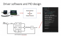
I'm a graduate student currently working on the neurobiology of addiction and pain, with an interest in the design of a novel thermal gradient ring that can be controlled between -5 degrees C and 60 degrees C (see the first attachment). Unfortunately, I'm definitely a novice when it comes to electrical design however I have a basic schematic of how I would like to power this device (see attachment 2). Essentially the device is a circular aluminum ring with 12 thermally isolate zones, each with a Peltier thermoelectric conducting (TEC) module underneath. I've talked to a few companies and my mentor, the current problem is I'm not sure how much power to give the TEC. I'm attaching the data specifics of the TEC, they are rated for Vmax 16V, I max 8.1 A, so I was thinking to power each one I would use a 15V/7A PSU (datasheet also attached).

I was going to run from the battery a positive parallel lead into the solid state relay, and from there attach the TEC. My question is do I need a voltage regulator between the solid state relay and the TEC? Or should I use some sort of buck converter/step down regulator? Essentially the TECs are powered on by the solid state relay from the company phidgets. I was going to pulse-width modulate the TECs by having thermocouplers registering the temperature in real time and the phidgets interface, control the switching on and off of the solid state relay. I'm just unsure of 1) if I need to regulate the voltage going into the TEC and 2) if this design is appropriate. Phidgets says that this can all be controlled via their VINT hub which would have the solid state relay, and the thermocouplers attached.

The reason why we are doing this is that I reached out to a company and they quoted me at $30,000 to build this but the parts I've put together it only costs roughly $1000 dollars. This device would open huge doors in the field of neuroscience by allowing us to measure thermal thresholds and tolerance in a multitude of paradigms. My sincerest apologies if I didn't explain something correctly, I'm kinda just learning as I go and this is definitely not my field. I tried searching on here for people using TECs but they are typically in refridgeration applications that don't apply and are a bit over my head. Any guidance is appreciated and I thank you all very much!
 

Attachments

MrAl

Joined Jun 17, 2014
11,389
Hi,

I am not entirely sure i understand your project completely i'll have to read it over again, but there are some basic things you might want to be aware of, and a question i have also.

First, since it sounds like there will be sensitive instrumentation involved you probably want to go with a linear power supply. That will eliminate switching noise which can be a problem. If you find the efficiency to be too bad you can always go with a switcher later but in cases where the data is so much more important than the efficiency a linear will provide a constant DC power source without much noise.

Then could you describe briefly what you intend to do with the TEC what is the function of that exactly?
A secondary less important question, will you be able to detect pain in humans AND small animals like shellfish? I would be very interested in that as i would like to finally put to rest the debate over if shellfish can or can not feel pain. From my own observations i say they do but a solid proof would be really really nice. This is a secondary question but would be interesting to find out.

I will read your original post again too a bit later.
 

Ian0

Joined Aug 7, 2020
9,670
I presume each section has a thermoelectric heater/cooler underneath it.
You need temperature feedback, so I would suggest a thermistor attached to the top surface.
The Peltier devices need a negative voltage to heat and a positive voltage to cool, so your power supply needs to be capable of both positive and negative output voltages.

First, I suggest you do some experiments with a bench power supply to see just how much power is required.

A couple of related points:
1) Why aluminium? Won't something with less thermal conductivity keep the zones better isolated?
2) Don't forget that the other side of the Peltier device needs a heatsink to be able to dissipate the heat that you have removed from the chamber.
 

Thread Starter

nsharf

Joined Jul 29, 2021
5
Hi,

I am not entirely sure i understand your project completely i'll have to read it over again, but there are some basic things you might want to be aware of, and a question i have also.

First, since it sounds like there will be sensitive instrumentation involved you probably want to go with a linear power supply. That will eliminate switching noise which can be a problem. If you find the efficiency to be too bad you can always go with a switcher later but in cases where the data is so much more important than the efficiency a linear will provide a constant DC power source without much noise.

Then could you describe briefly what you intend to do with the TEC what is the function of that exactly?
A secondary less important question, will you be able to detect pain in humans AND small animals like shellfish? I would be very interested in that as i would like to finally put to rest the debate over if shellfish can or can not feel pain. From my own observations i say they do but a solid proof would be really really nice. This is a secondary question but would be interesting to find out.

I will read your original post again too a bit later.
Hey, thank you so much for the reply! Sorry, I should have stated this but this device is for rats and the purpose is to measure thermal thresholds and tolerance for stimuli as they change with different conditions (i.e. inflammatory, neuropathic, and drug-withdrawal models). I will look into a linear power supply as they may be more helpful for our use. The TEC or Thermoelectric conductor is the actuator or the device that will actually heat up and/or cool down the aluminum piece above it. In the other reply, I will have the thermistor attached to measure the temperature of the aluminum.

Also to answer your question, shellfish do feel "pain" (it's more that they register painful-like stimuli). In preclinical research (i.e. animal research) we can't say definitively if an animal is experiencing pain because pain is a multimodal sensory and emotional process, but we state they experience pain-like phenomena and produce pain-related behaviors. There is evidence they don't only just register painful-like stimuli but also have prolonged responses to those stimuli (see the review attached!) :)
 

Attachments

Ya’akov

Joined Jan 27, 2019
9,070
Are you sure this ring is practical? Since the sections are not isolated, they will interact and the hotter ones will heat the cooler ones since aluminum is very good at thermal transmission. Will you really be able to get a useful gradient?

I think you may need to consider a PID controller and actively selecting heat or cool for sections to maintain heat, and possibly thermally isolating the sections. This is my impression, if it's been done elsewhere then I am wrong, but I am trying to picture how this will behave and can't.
 

Thread Starter

nsharf

Joined Jul 29, 2021
5
I presume each section has a thermoelectric heater/cooler underneath it.
You need temperature feedback, so I would suggest a thermistor attached to the top surface.
The Peltier devices need a negative voltage to heat and a positive voltage to cool, so your power supply needs to be capable of both positive and negative output voltages.

First, I suggest you do some experiments with a bench power supply to see just how much power is required.

A couple of related points:
1) Why aluminium? Won't something with less thermal conductivity keep the zones better isolated?
2) Don't forget that the other side of the Peltier device needs a heatsink to be able to dissipate the heat that you have removed from the chamber.

Hi Ian0 sorry I should have put that in the description but they will have case fans on the bottom to cool off the side of the ring that is supposed to heat up. The TECs have a hot and cold side and I should have also mentioned that half will be on the hot and half will be on the cool side. The case fans will be important and will also act like a white noise machine that helps calm the rats down.

I should have also mentioned although it is in the post abstractly that there will be a thermistor attached on the corner as we are going to fold a piece of the aluminum and attach it there. So for the TEC device themselves I misunderstood how they worked, I thought the positive was where the voltage went and the negative was the ground. The power supply I linked has a positive and negative terminal. Would you suggest then wiring the terminals in parallel and using independent solid-state relays (one for the positive terminal wired in parallel and one for the negative terminal wired in parallel) to power the TEC? That would be my approach. Also, do you think the current setup is okay, or do we need voltage regulators between the solid-state relay and each TEC? I think it should be fine but again, my understanding is limited when it comes to electronics.

Thank you so much for your help!!
 

MrAl

Joined Jun 17, 2014
11,389
Hey, thank you so much for the reply! Sorry, I should have stated this but this device is for rats and the purpose is to measure thermal thresholds and tolerance for stimuli as they change with different conditions (i.e. inflammatory, neuropathic, and drug-withdrawal models). I will look into a linear power supply as they may be more helpful for our use. The TEC or Thermoelectric conductor is the actuator or the device that will actually heat up and/or cool down the aluminum piece above it. In the other reply, I will have the thermistor attached to measure the temperature of the aluminum.

Also to answer your question, shellfish do feel "pain" (it's more that they register painful-like stimuli). In preclinical research (i.e. animal research) we can't say definitively if an animal is experiencing pain because pain is a multimodal sensory and emotional process, but we state they experience pain-like phenomena and produce pain-related behaviors. There is evidence they don't only just register painful-like stimuli but also have prolonged responses to those stimuli (see the review attached!) :)
Thanks for the article i will read that next. I already read the preface though and i can see they are still a little indeterminant about pain vs no pain in animals with pain here defined in the exact way it is defined for a human being. It appears that their idea is to redefine 'pain' for animals in a way that gives the appearance of pain similar to humans by way of short and long term reactions to stimuli that correlate to that of a human, which is probably the only way. After all, so far we can not ask a fish if it feels pain.
I dont know if the article goes into this but there is also some arguments based on similar brain structures with those of some animals matching that of humans at least in part.
My question was about the same that they bring up: do they react as a computer algorithm would react when trying to keep its container from harm, or do they have a very bad emotional experience along with that.
From what i have read and seen over the years i can notice that there is more of a consensus now that shellfish feel pain and that this consensus has grown over the years. It seems the more we learn the more likely it is that they have a bad experience during and possibly after pain. This conversation also took place some years ago with human babies, as it was believed that they did not feel pain, but now it is believed that they not only feel pain they feel it stronger than adults.
With this knowledge that seems to grow in favor of "true pain", it seems that it is better to err on the side of true pain than no pain. If we assume there is true pain then if we are wrong it's not a big deal, but if we assume no pain and are wrong then we are actually torturing animals of all kinds.

To this end i'd like to see a better method for killing shellfish other than dropping them into boiling water.
It is funny that a TV show i watched hinted on this topic a little when it had shown a lobster that has grown to many times it's normal size through some magic beam, and even developed human speech (ha ha it was a cartoonish show). The giant lobster grabbed a human and threw them into a big vat of boiling water, and then said,
"Oh dont worry those bubbles are just air escaping, they cant feel pain".
I thought that was funny :)

But back to the control issues. As you might know, thermistors are somewhat slow to respond so i cant say that would be the best measurement sensor. I think a thermal couple has faster response but maybe even a digital sensor if you can fit that in there. A digital sensor would be more accurate also and it can be read easily with a microcontroller. That's actually a more modern method thermistors are way old technology although the SMD type are faster having less mass, but still require careful Analog to Digital conversion at some point while the straight up digital sensors do not. In either case though i would think careful calibration is in order.

As far as response, as Yaakov mentioned, you probably need a decent controller. PID, State Variable, etc. The idea is that if you incorporate at least one derivative in the feedback you can sort of 'predict' the driven element's behavior in advance and that lets you drive it harder for a short time as it ramps up to where you really need it to be (the temperature in this case) and because you can drive it harder for a short time means that it ramps up to speed much faster than it would with just regular negative feedback which would be JUST the temperature reading and not the derivative of the temperature reading.

With that in mind, it makes sense to go with digital temperature sensors and at least one microcontroller. If you have never used a microcontroller before, now's the time to start :) There are uC boards out there that make this quite simple and i am sure you will learn how to use one fast. For one, there is the Arduinio. Many people choose that one for quick project turnaround. Programming is quite simple with it's reduced high level instruction set so you can create and modify algorithms within minutes. There is one called the "Nano" and as the name implies, it is very small, but still very powerful based on a very decent uC chip. It has a USB interface for programming and free programming software.

Please keep us informed as to the progress and end results and conclusions this is an interesting project.

Oh geeze i almost forgot to mention...
In mice it was proven that they can control their dopamine levels at least for some short time via some stimulus. Now it we could just prove the same in shellfish that would be another indicator i think of "true pain" in fish. If they can control their "feel good" chemical then they must have a sense of "feel good" vs "feel bad".
 
Last edited:

Ian0

Joined Aug 7, 2020
9,670
I would still recommend thermistors. The silicon inside the thermistor is not slow to respond. It responds immediately, but a lot of thermistors are packaged in expoy-resin beads which slows the response. The smallest bead thermistors will respond plenty fast enough for the application. The control system will need compensation which will slow it to below the speed that the heater can respond, there is no need for a "fast" temperature sensor.
What is the fastest temperature change you require?
The control system can be quite simple. FOr efficiency, I would suggest switching the Peltier device a few times a second using a MOSFET. You will also need to reverse the polarity to get it to cool. Than could be done with a DPDT relay.
All that is required for the control system is an op-amp as an error amplifier and a comparator to drive the MOSFET and relay, using a delta-sigma modulator technique, and a bit of logic to deal with the relay.

I would suggest a thin gauge of stainless steel for the construction. Thin would allow the heat to flow through the material but not along it. If you have it laser-cut and laser-scored along the fold lines, you can fold it into shape using your fingers.

I'll post a circuit diagram later.
 

MrAl

Joined Jun 17, 2014
11,389
I would still recommend thermistors. The silicon inside the thermistor is not slow to respond. It responds immediately, but a lot of thermistors are packaged in expoy-resin beads which slows the response. The smallest bead thermistors will respond plenty fast enough for the application. The control system will need compensation which will slow it to below the speed that the heater can respond, there is no need for a "fast" temperature sensor.
What is the fastest temperature change you require?
The control system can be quite simple. FOr efficiency, I would suggest switching the Peltier device a few times a second using a MOSFET. You will also need to reverse the polarity to get it to cool. Than could be done with a DPDT relay.
All that is required for the control system is an op-amp as an error amplifier and a comparator to drive the MOSFET and relay, using a delta-sigma modulator technique, and a bit of logic to deal with the relay.

I would suggest a thin gauge of stainless steel for the construction. Thin would allow the heat to flow through the material but not along it. If you have it laser-cut and laser-scored along the fold lines, you can fold it into shape using your fingers.

I'll post a circuit diagram later.
For a particular tiny chip thermistor (SMD) the thermal time constant is approximately 10 seconds. Do you really want to call that 'fast' ?
But maybe you can find a faster one. Post the part number we can take a look.

We'd also have to look at the digital types too though as to their time constant. I dont remember looking into that yet most of the apps i had to do did not require fast response (even a minute would be ok).

It's true you might do this with an op amp with carefully designed feedback (State Variable for example) but the modern way is to do it digitally.
 

Ian0

Joined Aug 7, 2020
9,670
10 seconds seems like fast enough for a heater - I doubt that the Peltier module is that quick, but 10 to 15 seconds is the typical thermal time constant for a bead thermistor IN AIR. https://docs.rs-online.com/6a46/0900766b813c0ed3.pdf
The value for a contact thermistor is almost ten times as fast. https://docs.rs-online.com/ad30/0900766b81554066.pdf
That is faster than the heater, meaning that the control circuit will almost certainly remain stable with little overshoot. A comparator would do it.

Doing it with a comparator and a power MOSFET would mean that a functional system could be got working in a matter of a few days. It could then be measured and improved upon where necessary. It would be far quicker than even the time it would take me to learn to use a new microprocessor board, and the TS said the hasn't used microprocessors before.

[In the case of a slow thermistor, the op-amp circuit would require two time constants, a pole at the heater time constant and a zero at the thermistor time constant. A state-variable filter is second order and would approach 180° phase shift so would most Alikely send the system unstable]
 

MrAl

Joined Jun 17, 2014
11,389
10 seconds seems like fast enough for a heater - I doubt that the Peltier module is that quick, but 10 to 15 seconds is the typical thermal time constant for a bead thermistor IN AIR. https://docs.rs-online.com/6a46/0900766b813c0ed3.pdf
The value for a contact thermistor is almost ten times as fast. https://docs.rs-online.com/ad30/0900766b81554066.pdf
That is faster than the heater, meaning that the control circuit will almost certainly remain stable with little overshoot. A comparator would do it.

Doing it with a comparator and a power MOSFET would mean that a functional system could be got working in a matter of a few days. It could then be measured and improved upon where necessary. It would be far quicker than even the time it would take me to learn to use a new microprocessor board, and the TS said the hasn't used microprocessors before.

[In the case of a slow thermistor, the op-amp circuit would require two time constants, a pole at the heater time constant and a zero at the thermistor time constant. A state-variable filter is second order and would approach 180° phase shift so would most Alikely send the system unstable]
Hello again,

Thanks for the reply i hope we can collectively help the OP with this project.

The time constant isnt the time it takes to respond, it's the time it takes to reach to within 37 percent of the final value. To reach to within 1 percent of the final value takes 5 time constants. So a device that has a time constant of 10 seconds takes 50 seconds to reach to within 1 percent of the actual temperature, and of course a device that has a time constant of 1.5 seconds takes 7.5 seconds to reach to within 1 percent of the actual temperature, but some caution about that 1.5 seconds. That 1.5 seconds is for when the sensor is immersed in water (and probably other liquids also).
But i dont think we got any specification on the required timing yet anyway so maybe we should wait for that. With instrumentation for experiments with nature you often want to instantiate the change as fast as possible to some decent level of accuracy, and this means we want to reach a decent level of accuracy usually in the shortest time possible. This would mean a search for the fastest measurement method would be a good idea unless this happens to have a very relaxed specification.

I am not sure where you got the idea that second order systems are unstable. Did you really mean to say that? Second order (and higher) systems are widespread and geeze i dont think we would be here if it wasnt
for second order (and higher) systems :)
Also, Yaakov suggested a PID controller which would normally be at least 2nd order.
So maybe you could restate what you meant by that.
 

Thread Starter

nsharf

Joined Jul 29, 2021
5
Are you sure this ring is practical? Since the sections are not isolated, they will interact and the hotter ones will heat the cooler ones since aluminum is very good at thermal transmission. Will you really be able to get a useful gradient?

I think you may need to consider a PID controller and actively selecting heat or cool for sections to maintain heat, and possibly thermally isolating the sections. This is my impression, if it's been done elsewhere then I am wrong, but I am trying to picture how this will behave and can't.
Hi Yaakov, thank you so much for the reply. I really dropped the ball on explaining certain things but yes, we would use the PID controller through a phidgets interface (see screenshot of the presentation where I put the basic flow of control for the device). The ring would have thermally isolate sections by ceramic tiles in between each zone. The idea is to use this in rats and have them find a preference temperature (which may differ depending on treatments/conditions) and then identify thermal threshold and tolerance. We are likely going to add layers where we can condition the animals to prefer a certain zone or pair it with an aversive stimulus.

Again my main issue is, do I need voltage regulators in between the TEC and the solid state relay? I'm going to look into what MOFSET is and as for the time that it takes to control, I'm not super worried about whether it takes 10 seconds to even 30 seconds for the device to heat up or cool. Again, there will a "hot" and "cold" side as the TECs can only be oriented with either side facing up towards the Aluminum.

To be honest I saw all the replies and will try to get to everyone. I'm absolutely overwhelmed and thankful for all the help! Seriously, I can't believe this got this much attention and I'm forever grateful for every response here!
 

Attachments

Thread Starter

nsharf

Joined Jul 29, 2021
5
10 seconds seems like fast enough for a heater - I doubt that the Peltier module is that quick, but 10 to 15 seconds is the typical thermal time constant for a bead thermistor IN AIR. https://docs.rs-online.com/6a46/0900766b813c0ed3.pdf
The value for a contact thermistor is almost ten times as fast. https://docs.rs-online.com/ad30/0900766b81554066.pdf
That is faster than the heater, meaning that the control circuit will almost certainly remain stable with little overshoot. A comparator would do it.

Doing it with a comparator and a power MOSFET would mean that a functional system could be got working in a matter of a few days. It could then be measured and improved upon where necessary. It would be far quicker than even the time it would take me to learn to use a new microprocessor board, and the TS said the hasn't used microprocessors before.

[In the case of a slow thermistor, the op-amp circuit would require two time constants, a pole at the heater time constant and a zero at the thermistor time constant. A state-variable filter is second order and would approach 180° phase shift so would most Alikely send the system unstable]
Hi Ian0! Thank you and Mr Al so much for the discussion. The original plan was to use a bead thermistor and with a PID design control the power to the TEC via the solid state relay. I got most of the idea from phidgets and their devices. Here is the video I watched explaining how their feedback loop works (
. When I contacted them they stated that the code can be controlled through their software and that controls the power to the TEC, all i do is code a pulse-width modulation based on the feedback from the thermistor. All of this is done through the VINT hub (https://www.phidgets.com/?tier=3&catid=2&pcid=1&prodid=643) that connects 4 of the thermocouple phidgets and one 16x solid state relay, also see the attached screenshot from my presentation. I'm willing to learn how to just use a microprocessor but the VINT hub seemed like a "plug and play" sort of device. As I stated to Yaakov the time to heat up and cool down isn't a major variable for us, as long as a steady-state is achieved within 30 seconds it should be fine. There are other TECs that I can order, just when I reached out to the company and described my idea, the HP-127-1.4-1.15-71 model was the one they recommended.

My apologies if I misunderstood how things worked, this is a bit over my head, but I've resolved to figure this out and make this device. I really believe in the application of it and am beyond grateful for all the help. I'll investigate MOSFETs and potentially look into using an arduino or something instead of phidgets.
 

Attachments

Top