Purposes of these diodes in a circuit

panic mode

Joined Oct 10, 2011
5,450
1. Remember even 9V can electrocute a person. Imagine the heart is connected to the 9V battery with only 100Ohm resistance. I=V/R = 9V/100 Ohm = 90mA enough to stop the heart. Remember the story of the sailorman with faulty multimeter who died from 9V battery.
for connect battery and 100 Ohm resistor to the heart, you would need to go through layers of flesh. That alone i would constitute serious injury. in my career i have handled many different power sources but never managed to rip someone's chest cavity to connect electrodes to the heart. i guess one could say that i am not that experienced...
and no, I don't recall sailor with multimeter story. I mean sailors were also explorers and of course they got killed left right and center. they were dying from everything, dawning, burning, freezing, crushing, being bitten, burned by lava, being hanged, speared, gunned down, bombed, exposure to diseases, malnutrition, rogue waves, meteors, STD, jealous husbands, jealous wives, etc. I suppose it is only right that one of them could have died a multimeter...

3. I know your point 8V will be what the input to the bottom IC will always see. But what if there is no diode. In the bottom . Won't 7.2V still be seen by the input of the IC? Or 50V + 7.2V? 57.2? What voltage would it exactly see? Thanks.
if there is a diode, diode would conduct and clamp that to +8V thus likely saving the IC. That is because Vf of the diode is nearly constant and Vs is a constant. So input at IC would be tied to something constant. in this case it does not matter what Vin+ is (except for R1 which could be getting hot or burning).

if there is no diode (diode is replaced by a short circuit) then IC input would see Vs which is 7.2V, regardless of what voltage is at Vin+ (0V, or 50V or 100V makes no difference - except for R1 which could be getting hot or burning).

if there is no diode (diode is replaced by an open circuit) then IC input would see nearly full voltage of 50V if the IC input is high impedance. if you model that impedance as a fixed resistor of not too high value, then voltage would be as if R1 and that resistor have formed a voltage divider.
1708911925060.png
 
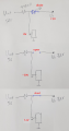
What could be the purpose of these diodes I actually saw in a bioamplifier circuit. The Vin+, Vin- at left are differential inputs, but why it is connected to the diodes? And why is the Vs+, Vs- (power supply) connected to the diodes at the right? AMP01 is the main amplifier with the V+, V- connected as shown.

View attachment 316115This is a typical arrangement (for the most part) of a bio type circuit. The 4.99k resistors are current limiting and the leads connecting this cct to a patient are also often quite resistive for the same reason. The point of the exercise is to limit the current for events such as a defibrillation pulse or other electrosurgery procedure. Incisions, as I understand it can be made with the scalpel connected to an RF generator (typically 500kHz) set to a power level that will cautorise small blood vessels, which makes the likelihood of an over voltage on a bio input quite high. In any event, that is usually what these diodes are for but there should be clamps somewhere to back this up. A defib pulse is 5kV and an ECG input for example may handle a peak of up to 50A depending on the series input resistance. Also be aware that the matching of these resistors is critical to the CMRR performance if the bio input is intended for a connection on the skin of the patient rather than an internal connection. For skin connections, the CMRR is literally a measure of the noise rejection. A typical bio amp will have a gain around 500 to 1000 and an input resistance in G Ohms or more so mains electric fields will produce a huge (common mode) signal when (differential) bio potentials are tiny. A CMRR of 90dB is about the minimum performance level required for an ECG input.
The 555 part of the circuit may be a detector for the high voltage event. In soe cases this can be done to trigger a reset of downstream filters or other dsp which might be saturated by the event and take too long to recover otherwise. Or it might be something altogether else. Just a possibility.
 
for connect battery and 100 Ohm resistor to the heart, you would need to go through layers of flesh. That alone i would constitute serious injury. in my career i have handled many different power sources but never managed to rip someone's chest cavity to connect electrodes to the heart. i guess one could say that i am not that experienced...
and no, I don't recall sailor with multimeter story. I mean sailors were also explorers and of course they got killed left right and center. they were dying from everything, dawning, burning, freezing, crushing, being bitten, burned by lava, being hanged, speared, gunned down, bombed, exposure to diseases, malnutrition, rogue waves, meteors, STD, jealous husbands, jealous wives, etc. I suppose it is only right that one of them could have died a multimeter...


if there is a diode, diode would conduct and clamp that to +8V thus likely saving the IC. That is because Vf of the diode is nearly constant and Vs is a constant. So input at IC would be tied to something constant. in this case it does not matter what Vin+ is (except for R1 which could be getting hot or burning).

if there is no diode (diode is replaced by a short circuit) then IC input would see Vs which is 7.2V, regardless of what voltage is at Vin+ (0V, or 50V or 100V makes no difference - except for R1 which could be getting hot or burning).

if there is no diode (diode is replaced by an open circuit) then IC input would see nearly full voltage of 50V if the IC input is high impedance. if you model that impedance as a fixed resistor of not too high value, then voltage would be as if R1 and that resistor have formed a voltage divider.

View attachment 316198
I suggest a closer look at the amplifiers data sheet. For an overvoltage event, there is usually a power or current limit allowance in that condition. So clamping hard to the power rail is not always absolutely necessary (although it seems bad practice not to). Also, diodes in forward conduction can take some time to fully conduct during which the forward voltage can be several volts (never seen anything more than around 5V and never for more than the shortest periods of time, we are talking about less than a few ns). If the diodes are smaller types and the protection relies on their surge rating then the normal forward voltage is going to be not relevant. Look at the curves for forward voltage versus forward current. A smaller diode is attractive for these input protection circuits because they have less capacitance which helps keep the inputs balanced and the CMRR less impacted. For the same reason the diodes are also biased off the supply. This widens the depletion region in the diodes which increases the 'd' in the equation C = (permittivity)A/d and so reduces the capacitance of the diode. This in turn reduces the variation of capacitance of the diodes to maintain the CMRR (by avoiding different input impedance) and keeps the pole formed by input resistance (skin is several 10's of kOhms) and the diode capacitance high enough not interfere with the signal band and again, not to unbalance the inputs for the sake of the CMRR.
CMRR is a common theme here, you might notice. It is critical to most bio amplifiers. And defib protection is a regulatory requirement for any medical device. So you must survive the 5kV nasty and then faithfully amplify the 1mV or less bio signal. Bio amps are a bitch!
 

Thread Starter

Gpand

Joined Dec 11, 2023
105
Pedant, please fix the format of your reply because your text merged with mine.

This is the source of the sailorman electrocuted by 9V battery that is even mentioned in the official Navy electrical safety guidelines

1999 Darwin Award: Resistance is Futile (darwinawards.com)

This is the reason I've spent a month installing galvanic isolators in my bioamplifiers even if they are completely powered by batteries.

Let's quote a relevant part:

" When we did the experiment in the electrical safety class to determine our body's resistance, we found a resistance of 500K Ohms. Using 9V and 500K Ohms in the equation, we come up with a current of 18 microAmps, below the "feel" threshold of 1mA. However, removing the insulation of skin from our curious sailor here, the resistance through the very good conducting electrolytes of the body is sharply lower. Around 100 ohms, in fact, resulting in a current of 90mA - sufficient to stop our sailor's heart and kill him. "

So imagine in biopotential work where we abrade the skin to connect the electrodes and the resistances reaches 100ohms. If the 9V power supply battery of your bioamplifier accidentally contact the input and 9V/100Ohm is reached and 90mA course though your body and pass through your heart. Then you are gone. Right?

If you don't agree with it. What scenerio then when batteries and abraded skin can electrocute you?
 
How could the excessive input signal be suppressed using diodes connected to the power supply? I know in surge protection, it is clamped to ground, but not to the power supply itself. Is the circuit about removing slow excessive voltages or sudden surges? Pls. explain in words.

Also in my circuit. There are no output diodes or ESD Current-Steering diodes. Only the input diodes are there. Is the output diodes function separate from the input diodes? Thanks.
Don't get hung up on the output protection. That circuit is for an opamp for which ESD can come from anywhere. you have a finished circuit with only the inputs exposed to surges. Do note the surge protection diodes though. In your case they may be located a little way off from the circuit you are looking at, but they are likely to be there somewhere unless the load on the 7.2V rail is big enough to absorb the expected surge current.
 
Pedant, please fix the format of your reply because your text merged with mine.

This is the source of the sailorman electrocuted by 9V battery that is even mentioned in the official Navy electrical safety guidelines

1999 Darwin Award: Resistance is Futile (darwinawards.com)

This is the reason I've spent a month installing galvanic isolators in my bioamplifiers even if they are completely powered by batteries.

Let's quote a relevant part:

" When we did the experiment in the electrical safety class to determine our body's resistance, we found a resistance of 500K Ohms. Using 9V and 500K Ohms in the equation, we come up with a current of 18 microAmps, below the "feel" threshold of 1mA. However, removing the insulation of skin from our curious sailor here, the resistance through the very good conducting electrolytes of the body is sharply lower. Around 100 ohms, in fact, resulting in a current of 90mA - sufficient to stop our sailor's heart and kill him. "

So imagine in biopotential work where we abrade the skin to connect the electrodes and the resistances reaches 100ohms. If the 9V power supply battery of your bioamplifier accidentally contact the input and 9V/100Ohm is reached and 90mA course though your body and pass through your heart. Then you are gone. Right?

If you don't agree with it. What scenerio then when batteries and abraded skin can electrocute you?
Gpand: my sincere apologies for the text merging.
Also, if your input circuits are powered, like for an isolation amplifier for example, there is still the chance of back feeding a DC potential into the patient. If this is a concern, a suitably rated safety capacitor as a dc block is your friend. But a contact resistance via skin of 100 Ohms, seriously? How scratched up was the skin!? Or how big were the electrodes? We use tiny 2mm long by 2.5mm diameter electrodes and get less than 100R but that is internal with the electrode swimmng in the salty soup. Surface electrodes like for an ECG are pretty small, I estimate around 1 or 2 cmsq.
 
for connect battery and 100 Ohm resistor to the heart, you would need to go through layers of flesh. That alone i would constitute serious injury. in my career i have handled many different power sources but never managed to rip someone's chest cavity to connect electrodes to the heart. i guess one could say that i am not that experienced...
and no, I don't recall sailor with multimeter story. I mean sailors were also explorers and of course they got killed left right and center. they were dying from everything, dawning, burning, freezing, crushing, being bitten, burned by lava, being hanged, speared, gunned down, bombed, exposure to diseases, malnutrition, rogue waves, meteors, STD, jealous husbands, jealous wives, etc. I suppose it is only right that one of them could have died a multimeter...


if there is a diode, diode would conduct and clamp that to +8V thus likely saving the IC. That is because Vf of the diode is nearly constant and Vs is a constant. So input at IC would be tied to something constant. in this case it does not matter what Vin+ is (except for R1 which could be getting hot or burning).

if there is no diode (diode is replaced by a short circuit) then IC input would see Vs which is 7.2V, regardless of what voltage is at Vin+ (0V, or 50V or 100V makes no difference - except for R1 which could be getting hot or burning).

if there is no diode (diode is replaced by an open circuit) then IC input would see nearly full voltage of 50V if the IC input is high impedance. if you model that impedance as a fixed resistor of not too high value, then voltage would be as if R1 and that resistor have formed a voltage divider.
View attachment 316198
Panic Mode: I do work with equipment that connects directly to the heart (via a catheter inserted at the groin into the femoral artery). The limit for such equipment of any current fed back into the heart or for the sum total of leakage currents back into the heart is 10uA. A pacing device (that triggers a heart beat with a signal directly into the heart) typically have a maximum current setting around 25mA and 25mA is a monster pacing pulse. The proverbial sledge hammer. If you can only manage a few milliamps but within the heart, that current is easily fatal. As for internal conduction, we are a sack of salty liquids and surprisingly conductive once you get through the skin. It is a fortunate fact for us electrical types, that skin is not at all a good conductor.
Gpand: external electrodes usually rely on some salty lube to improve contact with and conduction through the skin.
 
btw, if you think you understand Ohm and Kirchoffs Laws, try to chose resistor for following circuit. This can teach you a lot.
View attachment 316126
Really? The only complication I see here is that an incandescent lamp is a non linear load and highly dependent on the filament temperature. Other than that this is simply R = V/I = (24 - 6) / 0.5 = 36Ohms. Where is the complication? Or are you pointing out our OP appears to have some issues understanding circuits (diode claps in particular)?
 
Please tell me by what Ohm law principle why the resistor can never become 50V too when the input is 50V? And why the 50V can't get to the input of the IC at bottom.

View attachment 316125
In all seriousness, and I am not trying to be rude at all, but if you are having trouble understanding this, then the topic may be beyond your existing skill set.
As others have said, When the input voltage rises above Vs the diode steers the current away from the input when the diode is forward biased. The forward bias voltage of a diode (typically around 0.7V for a normal silicon diode) does not substantially increase even for substantial increases in the forward current through the diode. So once the diode is conducting the input is 'clamped' to the value of Vs and the voltage impressed across R1 is 50V - Vs and therefore, by Ohms law, the current in R1 is (50V - Vs)/R1. (ignoring the forward voltage of the diode here as it is small and relatively constant)
I have deliberately used my own version of this explanation. It is the same as many others in meaning. If this remains a mystery to you, I respectfully suggest, you think about the problem and the explanations given a bit more before you get agitated with the people trying to help you. :)
 

panic mode

Joined Oct 10, 2011
5,450
@Pedant Engineer
you may want to read it again. you would notice that question was not meant for you... or did you think that i needed help sorting this out?

the "complication" many noobs encounter is that they apply Ohms law incorrectly. all they see is the I=V/R and they plug into that formula whatever the values are mentioned in the question, without regard how they relate to the question. the OP had make same mistakes.

sadly i have seen this first hand many times. i even had (several) electrical engineers fail silly question like that during an interview. many pick V=24V and I=0.5A to get R=48 Ohm. when notified that answer is wrong, some have simply switched to another available voltage - the 6V to get 12 Ohm.

failure #1 is that voltage across resistor is neither 24V nor 6V but 18V (value not mentioned in the problem).
failure #2 is that most stop at that even though voltage drop and current are obviously large. one should also always calculate the power.
and even few that did go so far to calculate the power, had problem with computation (failure #3) or failed to add some safety margin to result (failure #4).

one thing is to fail difficult question, but failing ridiculously simple problem is actually a quick way to determine if candidate is deserves the time or one should move on and call the next one.
 

panic mode

Joined Oct 10, 2011
5,450
Let's quote a relevant part:

" When we did the experiment in the electrical safety class to determine our body's resistance, we found a resistance of 500K Ohms. Using 9V and 500K Ohms in the equation, we come up with a current of 18 microAmps, below the "feel" threshold of 1mA. However, removing the insulation of skin from our curious sailor here, the resistance through the very good conducting electrolytes of the body is sharply lower. Around 100 ohms, in fact, resulting in a current of 90mA - sufficient to stop our sailor's heart and kill him. "

So imagine in biopotential work where we abrade the skin to connect the electrodes and the resistances reaches 100ohms. If the 9V power supply battery of your bioamplifier accidentally contact the input and 9V/100Ohm is reached and 90mA course though your body and pass through your heart. Then you are gone. Right?

If you don't agree with it. What scenerio then when batteries and abraded skin can electrocute you?
as mentioned, i am not doing open heart surgery and applying electro stimuli to the heart. also and i am not in the business of trying to kill anyone with electricity. still that article is way far fetched, reads like urban legend. everything is vague (no name, no date, no location) but it is very specific about 9V being deadly, then it brings some calculations that start on a wrong premises.

so i looked it up and according to medical journals blood has pretty high conductivity (about 10x better then other tissue). they mention resistivity of 100 Ohm*cm. note that this is resistivity (rho), not resistance (R).
Resistance also includes length of conductor and the cross section. and i am pretty sure that if the story was true, sailor did not have arm span of 1cm (distance from one thumb to another) and that those two puncture wounds are probably connected by an artery with 1cm^2 cross section. even if that was the case, the heart would have to be really small to fit between two wounds.
 

panic mode

Joined Oct 10, 2011
5,450
regardless how i calculate this, the lowest value for body resistance I can come up with is closer to 1-2k than 100Ohm, even if really push the estimates to the crazy values. that is order of magnitude higher. So could it still be real, just an unlikely freak accident? maybe... not likely but suppose i can leave it at 'plausible'. perhaps he had an underlying condition or two.

1708919355916.png
 

Thread Starter

Gpand

Joined Dec 11, 2023
105
In all seriousness, and I am not trying to be rude at all, but if you are having trouble understanding this, then the topic may be beyond your existing skill set.
As others have said, When the input voltage rises above Vs the diode steers the current away from the input when the diode is forward biased. The forward bias voltage of a diode (typically around 0.7V for a normal silicon diode) does not substantially increase even for substantial increases in the forward current through the diode. So once the diode is conducting the input is 'clamped' to the value of Vs and the voltage impressed across R1 is 50V - Vs and therefore, by Ohms law, the current in R1 is (50V - Vs)/R1. (ignoring the forward voltage of the diode here as it is small and relatively constant)
I have deliberately used my own version of this explanation. It is the same as many others in meaning. If this remains a mystery to you, I respectfully suggest, you think about the problem and the explanations given a bit more before you get agitated with the people trying to help you. :)
I understood it already since 12 hours ago :)

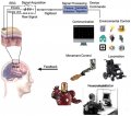
I'm concerned because I'm interested in BCI (Brain Computer Interface) so the electrodes will be connected to my body say the whole afternoon trying to control the augmented cytoskeleton. The amplifier is all battery operated so no problem with connecting with main accidentally.

With Panic Mode non-panic words DC post no problem. I guess I have to be more relax now. Is it true active amplifiers don't need any skin abration? I'm using passive electrodes and it's time consuming to put gel. When interfacing your nervous system with the augmented cytoskeleton, you don't have time to put gel as you jump into the suit and power on immediately.

BCI application.jpg
 
regardless how i calculate this, the lowest value for body resistance I can come up with is closer to 1-2k than 100Ohm, even if really push the estimates to the crazy values. that is order of magnitude higher. So could it still be real, just an unlikely freak accident? maybe... not likely but suppose i can leave it at 'plausible'. perhaps he had an underlying condition or two.

View attachment 316203
My apologies for answering the wrong person earlier.
I can only speak for the conductivity of blood and heart tissues and even then the values I use are scaled to the geometries of the electrode arrangements I am dealing with and then verified "in situ". To assess if the numbers are plausible, as you have, would take a lot more effort than I have motivation for right now. 1k to 2k sounds reasonable to me but I have no basis for that opinion other than to trust in your assessment, which I do.
 
I understood it already since 12 hours ago :)

I'm concerned because I'm interested in BCI (Brain Computer Interface) so the electrodes will be connected to my body say the whole afternoon trying to control the augmented cytoskeleton. The amplifier is all battery operated so no problem with connecting with main accidentally.

With Panic Mode non-panic words DC post no problem. I guess I have to be more relax now. Is it true active amplifiers don't need any skin abration? I'm using passive electrodes and it's time consuming to put gel. When interfacing your nervous system with the augmented cytoskeleton, you don't have time to put gel as you jump into the suit and power on immediately.

View attachment 316204
I can say with confidence, under no circumstances will a medical procedure for attaching electrodes to a human body ever require the skin to be abraded. You will just have to get good at applying the gel or come up with a new method to minimise the contact resistance. Brain signals are tiny even compared to external ECG signals. I do not envy you your task.
 
as mentioned, i am not doing open heart surgery and applying electro stimuli to the heart. also and i am not in the business of trying to kill anyone with electricity. still that article is way far fetched, reads like urban legend. everything is vague (no name, no date, no location) but it is very specific about 9V being deadly, then it brings some calculations that start on a wrong premises.

so i looked it up and according to medical journals blood has pretty high conductivity (about 10x better then other tissue). they mention resistivity of 100 Ohm*cm. note that this is resistivity (rho), not resistance (R).
Resistance also includes length of conductor and the cross section. and i am pretty sure that if the story was true, sailor did not have arm span of 1cm (distance from one thumb to another) and that those two puncture wounds are probably connected by an artery with 1cm^2 cross section. even if that was the case, the heart would have to be really small to fit between two wounds.
I could just add to Panic Modes point here, when a defib pulse is applied to the chest externally, the pulse if 5kV. I know a defib is a monster pulse but still, it takes 5kV at the surface to induce a current in the heart to effect a defib. Not sure that a 9V battery is likely to have all that much impact irrespective of the connection unless it is a direct cardiac connection or at least close to being that.
 
@Pedant Engineer
you may want to read it again. you would notice that question was not meant for you... or did you think that i needed help sorting this out?

the "complication" many noobs encounter is that they apply Ohms law incorrectly. all they see is the I=V/R and they plug into that formula whatever the values are mentioned in the question, without regard how they relate to the question. the OP had make same mistakes.

sadly i have seen this first hand many times. i even had (several) electrical engineers fail silly question like that during an interview. many pick V=24V and I=0.5A to get R=48 Ohm. when notified that answer is wrong, some have simply switched to another available voltage - the 6V to get 12 Ohm.

failure #1 is that voltage across resistor is neither 24V nor 6V but 18V (value not mentioned in the problem).
failure #2 is that most stop at that even though voltage drop and current are obviously large. one should also always calculate the power.
and even few that did go so far to calculate the power, had problem with computation (failure #3) or failed to add some safety margin to result (failure #4).

one thing is to fail difficult question, but failing ridiculously simple problem is actually a quick way to determine if candidate is deserves the time or one should move on and call the next one.
Sorry, it is not an interview and the power dissipation is not the issue. Why would you have a default mode of always calculating the power dissipation? In decades of design work, I calculate that which I need to know or need to check. If you always calculate the power dissipation then I expect you would also always check for temperature rise and assess the impact on reliability and long term value drift from thermal effects and maybe the noise contribution due to thermal effects.
And safety margins are also a highly variable requirement, closely related to reliability and value drift. I usually take these things into account in circuits and applications where that is relevant. Otherwise, it is just a silly exercise.
 
I understood it already since 12 hours ago :)

I'm concerned because I'm interested in BCI (Brain Computer Interface) so the electrodes will be connected to my body say the whole afternoon trying to control the augmented cytoskeleton. The amplifier is all battery operated so no problem with connecting with main accidentally.

With Panic Mode non-panic words DC post no problem. I guess I have to be more relax now. Is it true active amplifiers don't need any skin abration? I'm using passive electrodes and it's time consuming to put gel. When interfacing your nervous system with the augmented cytoskeleton, you don't have time to put gel as you jump into the suit and power on immediately.

View attachment 316204
That's good. You are welcome. ;)
 

Thread Starter

Gpand

Joined Dec 11, 2023
105
That's good. You are welcome. ;)
When you have time. Kindly check this thread about RFI interferences. because I'm worried the bio signals from skin would be distorted by many other frequencies. However, when I used a Netech EEG and ECG sine wave generator/simulator. I can create 10 microVolt sine wave and 1 mV sine wave on the BMA-200 bioamplifier. I can't see any noises. This was why I was asking in the thread the strength of RFI to distort the sine waves. So kindly give some figure the strength of RFI that can distort the sine wave generated. Thanks.

Strength of EMI to clip 1mV signal and RFI filters | All About Circuits
 

panic mode

Joined Oct 10, 2011
5,450
Why would you have a default mode of always calculating the power dissipation? In decades of design work, I calculate that which I need to know or need to check. If you always calculate the power dissipation then I expect you would also always check for temperature rise and assess the impact on reliability and long term value drift from thermal effects and maybe the noise contribution due to thermal effects.
And safety margins are also a highly variable requirement, closely related to reliability and value drift. I usually take these things into account in circuits and applications where that is relevant. Otherwise, it is just a silly exercise.
why wouldn't one calculate it? it is essential part of design process. the most common resistor sized are fraction of watt so limits can easily be exceeded. even to determine that calculation is not needed - one does the calculation. the thought process of evaluation of something need to be done or not is a calculation.;)
 
Top