Purposes of these diodes in a circuit

Thread Starter

Gpand

Joined Dec 11, 2023
105
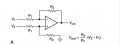
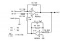
here is the circuit detail with components marked
View attachment 316120


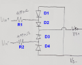
If Vin+ is large enough and positive, R1 and D2 will conduct. therefore voltage on input (right side of R1) will never be able to go above about +8V which is Vs+ value plus 0.7V for the forward drop across D2. the excess voltage will be absorbed by R1.

if the Vin+ happens to be large but negative, R1 and D1 will conduct. so the input voltage (right side of R1) will never be able to go below about -8V which is Vs- value and the voltage drop across D1.
in other words input voltage is clamped in this case to +/-8V even if the Vin+ is excessive.

Similarly, R2,D3,D4 work for clamping input signal to +/-8V

it has to be noted that current through diodes will try increasing Vs values so if the supply cannot absorb the change, Vs will grow to potentially dangerous limits.

to prevent that, TVS diodes are added as shown in my other post
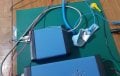
Panic mode. With the above circuit inside my device that can clamp high voltages in the input. Is it the same as ESD protection? How high surges can it protect? That is. Everytime I use my device. I always have to put ESD pad and wear ESD wrist and it is so hassle. Could the circuit protect against ESD so I don't have to use these cumbersome pads and wrist protectors anymore?

bma esd pads.jpg
 
Panic mode. With the above circuit inside my device that can clamp high voltages in the input. Is it the same as ESD protection? How high surges can it protect? That is. Everytime I use my device. I always have to put ESD pad and wear ESD wrist and it is so hassle. Could the circuit protect against ESD so I don't have to use these cumbersome pads and wrist protectors anymore?

View attachment 317134
As I said before, you are trying to design for ECG and EEG signals and everything in between, so some of your input circuits will probably have to be deigned to withstand a defibrillation pulse which is a monster 5kV pulse with plenty of punch and your EEG inputs are unlikely to perform very well with the standard diode clamps arrangement as protection, so something more sophisticated may be required. But as long as you can't differentiate an ESD event from the far more serious high voltage events you may be required to withstand, I think you need to do a lot more research into the requirements you have to meet for a medical device of this kind and then research how you might do that without ruining the performance of your inputs trying to faithfully detect and amplify a bio signal in the order of 10uV and all while the subject is ambulatory. Either that or accept that you have bitten off more than you can chew. I mean no offense, but this is not a newbie project. It will get a lot more difficult before you get it working properly. I have seen PhD students fail to get an ECG input stage to work and those are about the easiest of the inputs stages you will need.
 

Thread Starter

Gpand

Joined Dec 11, 2023
105
As I said before, you are trying to design for ECG and EEG signals and everything in between, so some of your input circuits will probably have to be deigned to withstand a defibrillation pulse which is a monster 5kV pulse with plenty of punch and your EEG inputs are unlikely to perform very well with the standard diode clamps arrangement as protection, so something more sophisticated may be required. But as long as you can't differentiate an ESD event from the far more serious high voltage events you may be required to withstand, I think you need to do a lot more research into the requirements you have to meet for a medical device of this kind and then research how you might do that without ruining the performance of your inputs trying to faithfully detect and amplify a bio signal in the order of 10uV and all while the subject is ambulatory. Either that or accept that you have bitten off more than you can chew. I mean no offense, but this is not a newbie project. It will get a lot more difficult before you get it working properly. I have seen PhD students fail to get an ECG input stage to work and those are about the easiest of the inputs stages you will need.
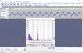
Hi, I'm not building any new equipments. I just needed all knowledge to justify whether to spent thousands of dollars on the software for the g.USBamp we already owned (we got it $1000 used from $16750). The software costs $4000 alone. We also got the BMA-200 already (bought used too). I'm asking whether the diodes are sufficient for ESD in daily ordinary table use so that I don't have to keep putting the ESD pads and wear ESD wrist bands. We are not using it any patients. It's part of physics experiments (our company moving forward relies on the results of the experiments) and we need equipment that can resolve 10 microVolt with 1000Hz bandwidth. Initially we thought 1milliVolt is sufficient, but not. So we both focus on 10uV scale now. The following is the output from the Netech simulator using 10uV, 50Hz. The reason 50Hz source is used because the simulator only has 0.1Hz, 2Hz, 5hz, 50Hz, 60Hz setting. And I can't chose 60Hz because the Audacity notch filter can totally null all amplitude.

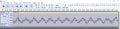
10uv 50hz bma 1000hz 50000 gain audacity plot spectrum.JPG


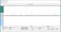
The following is output from the $16750 g.USBamp

netech 10uv 50hz usbamp 1000Hz ac filter off.JPG


Which equipment do you think is better? Presently I'm learning FFT how to remove the noises. I don't put the equipment always on the table because I have kids. We don't have exclusive lab yet and we don't intend to buld any from scratch. I only put the devices on table when the kids are outside, hence I don't want to keep installing the ground wires from window connected to the ESD pads and wrist band. So please tell me if the diodes are sufficient for ESD from fingers touching the leads, or I have to put the ESD pads and wear ESD band everytime I put them on table. Thanks.
 

Attachments

Hi, I'm not building any new equipments. I just needed all knowledge to justify whether to spent thousands of dollars on the software for the g.USBamp we already owned (we got it $1000 used from $16750). The software costs $4000 alone. We also got the BMA-200 already (bought used too). I'm asking whether the diodes are sufficient for ESD in daily ordinary table use so that I don't have to keep putting the ESD pads and wear ESD wrist bands. We are not using it any patients. It's part of physics experiments (our company moving forward relies on the results of the experiments) and we need equipment that can resolve 10 microVolt with 1000Hz bandwidth. Initially we thought 1milliVolt is sufficient, but not. So we both focus on 10uV scale now. The following is the output from the Netech simulator using 10uV, 50Hz. The reason 50Hz source is used because the simulator only has 0.1Hz, 2Hz, 5hz, 50Hz, 60Hz setting. And I can't chose 60Hz because the Audacity notch filter can totally null all amplitude.

View attachment 317517


The following is output from the $16750 g.USBamp

View attachment 317516


Which equipment do you think is better? Presently I'm learning FFT how to remove the noises. I don't put the equipment always on the table because I have kids. We don't have exclusive lab yet and we don't intend to buld any from scratch. I only put the devices on table when the kids are outside, hence I don't want to keep installing the ground wires from window connected to the ESD pads and wrist band. So please tell me if the diodes are sufficient for ESD from fingers touching the leads, or I have to put the ESD pads and wear ESD band everytime I put them on table. Thanks.
If you are working on electronics with the lid off the box, it is generally considered good practice to wear an anti static wrist or ankle band.
Other than that, at this distance and with all the unknowns, it is impossible for me to say any more than that without potentially misguiding you. From what you have said before and what you say now, I think you may already be misguided. You seem to be frantically working on something that has a spec and purpose that keeps changing. I think you need to slow down and work out exactly what it is you are trying to do. If you can't do that, then what is your target? How do you know when you are finished? How do you know you have met the requirements for the thing to function correctly. There is a world of difference between a bio signal of 10uV and a bio signal of 1mV and another world of difference based on sensing location, conditions etc etc.
Until you know what it is you are trying to achieve, you cannot ask general or generic questions and get meaningful answers. We tried that, remember? It does not work. You need more specific advice which needs more specific questions which will need more specific details, spec etc etc of the thing you are trying to create.
I don't have time to help you with all of that. But I think and strongly suggest that you make the time to define your project before you go any further.
 

Thread Starter

Gpand

Joined Dec 11, 2023
105
here is the circuit detail with components marked
View attachment 316120


If Vin+ is large enough and positive, R1 and D2 will conduct. therefore voltage on input (right side of R1) will never be able to go above about +8V which is Vs+ value plus 0.7V for the forward drop across D2. the excess voltage will be absorbed by R1.

if the Vin+ happens to be large but negative, R1 and D1 will conduct. so the input voltage (right side of R1) will never be able to go below about -8V which is Vs- value and the voltage drop across D1.
in other words input voltage is clamped in this case to +/-8V even if the Vin+ is excessive.

Similarly, R2,D3,D4 work for clamping input signal to +/-8V

it has to be noted that current through diodes will try increasing Vs values so if the supply cannot absorb the change, Vs will grow to potentially dangerous limits.

to prevent that, TVS diodes are added as shown in my other post
Hi I need to remove the 2 resistors by shorting them bec they are contributing to thermal noise. Please tell me. If I shorted the 2 resistors. What must I do to the diodes? Short all of them as well and cut the Vs+, Vs-? What if all of them remain and Id just short the 2 resistors? Pls confirm before I do it. Thanks.
 
Hi I need to remove the 2 resistors by shorting them bec they are contributing to thermal noise. Please tell me. If I shorted the 2 resistors. What must I do to the diodes? Short all of them as well and cut the Vs+, Vs-? What if all of them remain and Id just short the 2 resistors? Pls confirm before I do it. Thanks.
I do not understand why you would need to ask that. This is a very simple concept in overvoltage protection and if it is beyond you I wonder how you would cope with the rest of the hardware design. I am not being unkind, just frank and honest. Two current limiting resistors and some steering diodes and you don't understand it?
Smaller value R is quieter, shot noise from the diodes may also be an issue. If you need O/V protection, you may need something more carefully designed / more sophisticated.
 

Thread Starter

Gpand

Joined Dec 11, 2023
105
I do not understand why you would need to ask that. This is a very simple concept in overvoltage protection and if it is beyond you I wonder how you would cope with the rest of the hardware design. I am not being unkind, just frank and honest. Two current limiting resistors and some steering diodes and you don't understand it?
Smaller value R is quieter, shot noise from the diodes may also be an issue. If you need O/V protection, you may need something more carefully designed / more sophisticated.
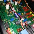
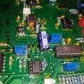
I'm not building any new circuit. Just using existing one. Someone told me to replace the LF412 (with 25nV/Sqrt (Hz) with the OPA2132P (with 8nV/Sqrt (Hz) noise and there is moderate noise improvement as seen in REW RTA. So I plan to see what would happen if the resistors would be removed. What if I just put jumper in the resistors without cutting the diodes (besides the blue capacitor below) and Vs+, Vs- just to how much is the further decrease in the noise. Would that temporarily jumpers in the 2 resistors (in original schematic) affect it drastically (with the diode and Vs+,Vs- not cut)? I just want to make sure and not ruin the $1595 equipment.

opa.jpg
 
I'm not building any new circuit. Just using existing one. Someone told me to replace the LF412 (with 25nV/Sqrt (Hz) with the OPA2132P (with 8nV/Sqrt (Hz) noise and there is moderate noise improvement as seen in REW RTA. So I plan to see what would happen if the resistors would be removed. What if I just put jumper in the resistors without cutting the diodes (besides the blue capacitor below) and Vs+, Vs- just to how much is the further decrease in the noise. Would that temporarily jumpers in the 2 resistors (in original schematic) affect it drastically (with the diode and Vs+,Vs- not cut)? I just want to make sure and not ruin the $1595 equipment.

View attachment 318651
You could calculate the resistor noise or for a more specific number look the part up and get the data for it. The diodes you could also check their data sheet remembering that, as you would already know, the noise contribution of both things is a function of temperature. To handle a signal down to 10uV takes special care and careful engineering. So go do the engineering and you will be able to answer your own questions.
 

schmitt trigger

Joined Jul 12, 2010
2,276
What if I just put jumper in the resistors without cutting the diodes (besides the blue capacitor below) and Vs+, Vs- just to how much is the further decrease in the noise. Would that temporarily jumpers in the 2 resistors (in original schematic) affect it drastically (with the diode and Vs+,Vs- not cut)? I just want to make sure and not ruin the $1595 equipment.
I am old enough to have started driving before seat belts were mandatory. There was a lot of pushback against using seat belts when these first appeared in autos. I had several classmates who bragged that they had been driving without belts for over a year and were very happy about their "feat". My answer to them was always: "Have you had an accident?"

Thus my DISCLAIMER; For the purpose of only testing your theory, and doing said test with all the correct ESD mitigation procedures, and if you are also lucky while performing the test, then nothing should happen. But no-one here can 100% guarantee that a mishap won't happen, and you won't ruin your $1595. Proceed at your own risk, people here have explained very thoroughly the purpose of the circuitry.
 
Last edited:

Thread Starter

Gpand

Joined Dec 11, 2023
105
for connect battery and 100 Ohm resistor to the heart, you would need to go through layers of flesh. That alone i would constitute serious injury. in my career i have handled many different power sources but never managed to rip someone's chest cavity to connect electrodes to the heart. i guess one could say that i am not that experienced...
and no, I don't recall sailor with multimeter story. I mean sailors were also explorers and of course they got killed left right and center. they were dying from everything, dawning, burning, freezing, crushing, being bitten, burned by lava, being hanged, speared, gunned down, bombed, exposure to diseases, malnutrition, rogue waves, meteors, STD, jealous husbands, jealous wives, etc. I suppose it is only right that one of them could have died a multimeter...


if there is a diode, diode would conduct and clamp that to +8V thus likely saving the IC. That is because Vf of the diode is nearly constant and Vs is a constant. So input at IC would be tied to something constant. in this case it does not matter what Vin+ is (except for R1 which could be getting hot or burning).

if there is no diode (diode is replaced by a short circuit) then IC input would see Vs which is 7.2V, regardless of what voltage is at Vin+ (0V, or 50V or 100V makes no difference - except for R1 which could be getting hot or burning).

if there is no diode (diode is replaced by an open circuit) then IC input would see nearly full voltage of 50V if the IC input is high impedance. if you model that impedance as a fixed resistor of not too high value, then voltage would be as if R1 and that resistor have formed a voltage divider.

View attachment 316198

I regretted not asking above what happened if there was no resistor. Since the resistor gets the full 42V and without it, does it mean the wire get the full 42v? but a wire has no resistance, so what happened..Pls tell me guys one last time before i short the resistors in the actual circuit. Thank you.
 
I'm not building any new circuit. Just using existing one. Someone told me to replace the LF412 (with 25nV/Sqrt (Hz) with the OPA2132P (with 8nV/Sqrt (Hz) noise and there is moderate noise improvement as seen in REW RTA. So I plan to see what would happen if the resistors would be removed. What if I just put jumper in the resistors without cutting the diodes (besides the blue capacitor below) and Vs+, Vs- just to how much is the further decrease in the noise. Would that temporarily jumpers in the 2 resistors (in original schematic) affect it drastically (with the diode and Vs+,Vs- not cut)? I just want to make sure and not ruin the $1595 equipment.

View attachment 318651
There is an Analog Devices AMP01 in there. What is the LF412 doing in the signal chain? And is this the equipment you paid $1600 for? This looks to be a design from the 80's or early 90's except for one or two parts such as the Omron DC/DC give me pause for thought. If they are still milking the design at this dollar value after 30 odd years they are doing very well with it! But you'd think the design was mature enough not to need IC sockets or at least for what they charge, machined pin sockets instead of these cheap and nasty sockets popular with hobbyist stores. Who would put a high performance IA in a cheap and nasty socket? Tsk tsk.
 

Thread Starter

Gpand

Joined Dec 11, 2023
105
There is an Analog Devices AMP01 in there. What is the LF412 doing in the signal chain? And is this the equipment you paid $1600 for? This looks to be a design from the 80's or early 90's except for one or two parts such as the Omron DC/DC give me pause for thought. If they are still milking the design at this dollar value after 30 odd years they are doing very well with it! But you'd think the design was mature enough not to need IC sockets or at least for what they charge, machined pin sockets instead of these cheap and nasty sockets popular with hobbyist stores. Who would put a high performance IA in a cheap and nasty socket? Tsk tsk.
according to one person:

"The Lf412 is a JFET input amplofier and as such has very high impedance, very low bias current and very low current noise. This allows it to have consistent performance even with a very high source impedance. This is why it is used as the input stage.

The AMP01 has more bias current and more current noise. These will limit performance and introduce errors and noise with a high impedance signal source. With the problems that come with modifying an existing circuit which has been factory trimmed for precision, I don't think a major modification like bypassing the input stage is going to be a good Idea.The BF412 in the BMA-200 acts as a pre-amplifier with gain of 2 and very high input impedance. It also provides trimming for CMRR and DC offset. Due to its near infinite input impedance and very low bias current, it has near zero current noise, so is ideal for buffering very high impedance signal sources."

"

If you want to reanalyse your amplifier to see what changing various components makes then, I think main noise sources in the signal path are:
Source resistance (e.g. 10 kOhm)
2x 5k protection resistors
2x op amps (20 nV/sqrt Hz for the original LF412)
Instrumentation amp (5 nV/sqrt Hz for the AMP01).

You are interested in a bandwidth of 1 kHz:
So the calculation becomes:
10k Source resistance: 0.13 * Sqrt (10000) * Sqrt (BW) = 411 nV rms
2x 5k Protection resistors: Sqrt(2) * 0.13 * Sqrt (5000) * Sqrt (BW) = 411 nV rms
2x OP amps: Sqrt(2) * 20 * Sqrt (BW) = 894 nV rms
I amp: 5 * Sqrt (BW) = 158 nV rms

The noise powers sum:
Total = Sqrt (411 ^2 + 411 ^2 + 894 ^2 + 158 ^2) = 1078 nV rms"
 

Thread Starter

Gpand

Joined Dec 11, 2023
105
don't miss message above. i need to milk any performance out of the BMA-200 because i also own the $16750 gtec USBamp. But I still can't afford its $3000 software to run it.

going back to the question what would happen if the resistors were removed.

here is my initial guess of the effects when the resistors will be removed (see previous sketch).

For normal use where the input voltage would be less than the forward bias voltage of the diodes (less than 0.7 Volts). There would be no harmful effects even if the diodes remain in place and the 2 resistors removed. Right?

But for surges or ESD events where the diodes conduct producing voltage potential of 8V (source is Ni-MH rechargeable batteries)-0.7 (diode) = 7.3 volts. The higher input surge voltage of say 50V can charge the power source or rechargeable batteries. Can momentary charging by the surges/ESD cause the batteries to explode?

What ESD protection devices do you know that don't use any resistor in series to the source? I have to avoid any resistors to eliminate any noises since I need ultra low noise sensor.
 

LadySpark

Joined Feb 7, 2024
194
don't miss message above. i need to milk any performance out of the BMA-200 because i also own the $16750 gtec USBamp. But I still can't afford its $3000 software to run it.

going back to the question what would happen if the resistors were removed.

here is my initial guess of the effects when the resistors will be removed (see previous sketch).

For normal use where the input voltage would be less than the forward bias voltage of the diodes (less than 0.7 Volts). There would be no harmful effects even if the diodes remain in place and the 2 resistors removed. Right?

But for surges or ESD events where the diodes conduct producing voltage potential of 8V (source is Ni-MH rechargeable batteries)-0.7 (diode) = 7.3 volts. The higher input surge voltage of say 50V can charge the power source or rechargeable batteries. Can momentary charging by the surges/ESD cause the batteries to explode?

What ESD protection devices do you know that don't use any resistor in series to the source? I have to avoid any resistors to eliminate any noises since I need ultra low noise sensor.
When you remove the resistors, it will remove the gain constant Rin for tor the op amp. The resistor are there to set the gain and input impedance. Noise is usually not an issue with those resistors. Because they would have used low PPM resistors and match them. Noise is not always caused by parts. Some noise comes from +V and -V supplies not being equal but opposite (like +14.75V and -14.75V respectively on +15V and -15V supplies )

The input is one of the standard balanced inputs. The classic name for it was called non-loading dc coupled balanced input. Normally this input is used in passive inputs, but I have seen others use it in line applications however, they are not universal to all balanced line outputs. I've notice this circuit popping up in studio monitors and of course, it has interfacing issues with some of the monitor controllers because they are impedance balance type that needs shunt termination for their signal - output to work correctly.

The diodes are standard input protection. They prevent damage caused by plugging in something to the inputs with it being turned on. Granted the op amps do have them internally, but its common practice to put a set externally so that the failure of the diode is external. So, its up to you , do you want to change a $0.20 diode or a $5 op amp. That is why you should leave them in.

To answer the last question, there is not enough current in a static discharge to cause adverse effects to a power supply of any kind.
 

Thread Starter

Gpand

Joined Dec 11, 2023
105
When you remove the resistors, it will remove the gain constant Rin for tor the op amp. The resistor are there to set the gain and input impedance. Noise is usually not an issue with those resistors. Because they would have used low PPM resistors and match them. Noise is not always caused by parts. Some noise comes from +V and -V supplies not being equal but opposite (like +14.75V and -14.75V respectively on +15V and -15V supplies )

The input is one of the standard balanced inputs. The classic name for it was called non-loading dc coupled balanced input. Normally this input is used in passive inputs, but I have seen others use it in line applications however, they are not universal to all balanced line outputs. I've notice this circuit popping up in studio monitors and of course, it has interfacing issues with some of the monitor controllers because they are impedance balance type that needs shunt termination for their signal - output to work correctly.

The diodes are standard input protection. They prevent damage caused by plugging in something to the inputs with it being turned on. Granted the op amps do have them internally, but its common practice to put a set externally so that the failure of the diode is external. So, its up to you , do you want to change a $0.20 diode or a $5 op amp. That is why you should leave them in.

To answer the last question, there is not enough current in a static discharge to cause adverse effects to a power supply of any kind.
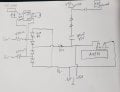
You haven't seen the wider schematic shared in message #1. The LF412 doesn't need the gain constant Rin. The purpose of the resistors is for the diodes clamping voltage during surge/ESD. If you remove the resistors and let's say they are really not for the LF412. What would happen to the diodes and the clamping voltage thing? Nothing? Because I plan to short the resistors but the act of shorting might damage the pcb a bit so want to know first what would happen. In the following sketch, the op am LF412 has 1 IN-, 1IN+ on the left, I mistakenly wrote 2. They are to condition the input to the primary AMP01.

Let's say you were right the LF412 needs the resistor (does it really?). Then what resistor do the diodes used in the voltage clamping thing during ESD?

diodes schem.jpg
 

LadySpark

Joined Feb 7, 2024
194
You haven't seen the wider schematic shared in message #1.
yes I have its a standard circuit that is referred to now these days as a 'Difference Amp' which is really non descriptive compared to the older name: non loading directly coupled balanced input op amp.

I think you have the diodes drawn wrong, even though they will provide the function the same after the resistor as well as before them.
 

Attachments

Thread Starter

Gpand

Joined Dec 11, 2023
105
yes I have its a standard circuit that is referred to now these days as a 'Difference Amp' which is really non descriptive compared to the older name: non loading directly coupled balanced input op amp.

I think you have the diodes drawn wrong, even though they will provide the function the same after the resistor as well as before them.
You mean the LF412 is sharing the same resistor as the ESD diodes? how do they synchronize what resistor value to use? or do the ESD diodes just follow what resistor is being used by the LF412?
 

LadySpark

Joined Feb 7, 2024
194
You mean the LF412 is sharing the same resistor as the ESD diodes? how do they synchronize what resistor value to use? or do the ESD diodes just follow what resistor is being used by the LF412?
The ESD diodes are invisible to the circuit and do not play in any role in the operation of it.
A little strange, seeing your schematic. Its almost like they are parallel the input as AMP1 is just another insturment amp which those has to have external esd protection. But you didn't draw signal + and signal - inputs.
 

Thread Starter

Gpand

Joined Dec 11, 2023
105
The ESD diodes are invisible to the circuit and do not play in any role in the operation of it.
A little strange, seeing your schematic. Its almost like they are parallel the input as AMP1 is just another insturment amp which those has to have external esd protection. But you didn't draw signal + and signal - inputs.
What do you mean "The ESD diodes are invisible to the circuit and do not play in any role in the operation of it."? member "Panic Mode" made extensive analysis and explanation of them in earlier messages in this thread. See below. Please comment what you think.

clamping voltage.png

Panic mode wrote:

"If Vin+ is large enough and positive, R1 and D2 will conduct. therefore voltage on input (right side of R1) will never be able to go above about +8V which is Vs+ value plus 0.7V for the forward drop across D2. the excess voltage will be absorbed by R1.

if the Vin+ happens to be large but negative, R1 and D1 will conduct. so the input voltage (right side of R1) will never be able to go below about -8V which is Vs- value and the voltage drop across D1.
in other words input voltage is clamped in this case to +/-8V even if the Vin+ is excessive.

Similarly, R2,D3,D4 work for clamping input signal to +/-8V

it has to be noted that current through diodes will try increasing Vs values so if the supply cannot absorb the change, Vs will grow to potentially dangerous limits.

to prevent that, TVS diodes are added as shown in my other post
"

lf412 amp01.jpg
 
Top