 Facebook
 Google
 GitHub
 Linkedin
I had threatened to post this awhile back & since I finally got my panel meter installed, thought I'd share what the AAC gang has helped me develop over the past few months.
The Project:
Thanks to all the AAC members who have assisted me along the way. Considering I'd never drawn a schematic or done a board layout before joining this site, I definately couldn't have gotten this far without their patience & much needed guidance.
To the administrator/moderators: super web-site. Thank-you.
Doug
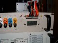
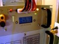
OT: The last photo is a bit blurry, but I wanted to show the backlight of the LCD is blue. It washed out in the other photos.
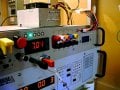
The Project:
I've been building a pseudo-Rack Mount PSU that combines an ATX PSU breakout & a variable voltage/selectable current PSU in one unit. The hardware components are mostly electronic surplus. Good example is the case: it was a Catel optical comm unit from the 80s. Lots of sanding, body putty, drilling/cutting/priming/painting/labeling later, you'd never know what it started as. The unit is up and running & I didn't even blow myself up or put out an eye! 
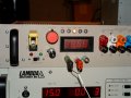
The ATX Breakout:
The ATX component changed quite a bit from the original plan after I found a commercially available tester. I modified it (read that: completely disassembled it) for this application. We had a bit of discussion in the Projects Forum about setting the minimum load resistance to have the ATX latch on with the correct voltages on all lines, so I followed the recommendations there & did a little experimentation to come up with the load I'm using for my particular supply. Other things I did were remove the peizo alarm, installed POST and Standby LEDs, & then ran everything to a fuse panel before connecting the outs to the binding posts. I painted the posts to match the standard ATX line-out color.
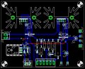
The Adjustable Side:
I used different colored superbright LEDs for each current indicator position. You may note the resistor value for IC1 in the schematic seems unusual. I changed the LED's LM317T current set resistor to 150Ω to drop them down to around 8mA. I originally had gone with a 68Ω to run the LEDs at about 18mA - way too bright for this application. The lower current keeps me from blinding myself!
AAC also helped solve the voltage adjust problems I was having. The original plan followed standard schemes of a single pot, typically 5k, to swing the voltage. It didn't behave in a desired manner & following recommendations from here I ended up using a double gang (1kΩ & 500Ω) pot. It works well. The resistor values & sizes for the current limiting 317 (IC2) are straight forward Ohm's law stuff. The panel meter set-up was covered in a recent, separate post.
The work is still in progress as I refine the power supply for the variable side of the unit. I figure it will be a SMPS, 24V max, 2 Amp. I want some reserve voltage/amperage on the SMPS so it's not working too hard when I'm boarding things in the 19.99V/1A setting. I'm currently powering the board off one of the Lambda 15V supplies. I also will make my own PCB for the final versions - it's all currently on a veroboard (lol, which was nuts, but hey, I'm learning, lol).AAC also helped solve the voltage adjust problems I was having. The original plan followed standard schemes of a single pot, typically 5k, to swing the voltage. It didn't behave in a desired manner & following recommendations from here I ended up using a double gang (1kΩ & 500Ω) pot. It works well. The resistor values & sizes for the current limiting 317 (IC2) are straight forward Ohm's law stuff. The panel meter set-up was covered in a recent, separate post.
Thanks to all the AAC members who have assisted me along the way. Considering I'd never drawn a schematic or done a board layout before joining this site, I definately couldn't have gotten this far without their patience & much needed guidance.
To the administrator/moderators: super web-site. Thank-you.
Doug
OT: The last photo is a bit blurry, but I wanted to show the backlight of the LCD is blue. It washed out in the other photos.
Attachments
-
 52.9 KB Views: 455
 -
 147 KB Views: 371
 -
 68.8 KB Views: 358
 -
 41.3 KB Views: 348
 -
 51.2 KB Views: 283
 -
 46.3 KB Views: 289
Last edited:


