Project details Flyback convertor 800v with auxiliary supply output 50w 18v

Thread Starter

aman_zman

Joined Jun 4, 2026
6
Issue : 18V 50w output is achieved the issue not able to maintain 18v 50w constant
Netlist:
* C:\Users\Mohammed Aman\Downloads\FlyBack-AD-5 W.asc
* Generated by LTspice 26.0.2 for Windows.
R1 N012 0 .22
C1 N019 0 220p
C2 N017 0 .1µ
C3 N016 N015 .01µ
R2 N015 N011 200k
R3 N017 N019 12K
R4 N011 0 20k
R5 N012 N018 1k
R6 N014 N013 12
R7 N006 N011 124k
C4 N006 0 .22µ
C5 N007 0 100p
D1 N007 N006 BAT54
C6 N005 0 22µ
R8 N010 N005 39
D2 N008 N010 BAT54
R9 IN N018 1.32Meg
R10 IN N003 27k
C7 IN N003 470p
L1 N001 0 98µ Rser=.05 Rpar=2K
L2 N009 0 12µ Rser=.1 Rser=1m
L3 N004 IN 450µ Rser=.05 Rpar=5K
D3 N001 N002 MBRS340
C8 N002 0 14.8µ Rser=.1
L4 N002 OUT 1µ
C9 OUT 0 14.8µ Rser=.1
V1 IN 0 800
D4 0 N005 BZX84C15L
D5 N004 N003 MURS320
R12 N008 N007 500
R13 IN N005 400K
X§U1 N016 N011 N018 N019 0 N013 N005 N017 LT1241 ;§pnba COMP)FB)Isense)Rt/Ct)GND)Output)Vcc)Vref
D6 0 N013 BAT54
X§U2 N004 N014 N012 N012 NC_01 NC_02 IMZA120R014M1H_L3 ;§pnba DRAIN)GATE)SOURCE)SOURCESENSE)TJ)TCASE
R11 OUT 0 6.48
R14 N009 N008 4.7
.model D D
.lib C:\Users\Mohammed Aman\AppData\Local\LTspice\lib\cmp\standard.dio
K1 L1 L2 L3 .98
.tran 3m
* Library below included based on ModelFile attribute of instance X§U2 (C:\Users\Mohammed Aman\Downloads\Infineon-CoolSiC_1200V_Gen1_Trench_MOSFET-SPICE-v01_05-EN\IMZA120R014M1H_L3.asy)
.lib IMW-IMZA120RXXXM1H_7-40mOhm_v1.4.lib
* Library below included based on ModelFile attribute of instance X§U1 (C:\Users\Mohammed Aman\AppData\Local\LTspice\lib\sym\PowerProducts\LT1241.asy)
.lib LT1241.sub
.backanno
.end
 

Irving

Joined Jan 30, 2016
5,195
Welcome to AAC!

Please attach the .ASC file plus the .asy and .lib files for the U2 MOSFET ( Infineon-CoolSiC_1200V_Gen1_Trench_MOSFET-SPICE-v01_05-EN\IMZA120R014M1H_L3.asy, IMW-IMZA120RXXXM1H_7-40mOhm_v1.4.lib )
 

ronsimpson

Joined Oct 7, 2019
4,777
Issue : 18V 50w output is achieved the issue not able to maintain 18v 50w constant
In SPICE (LTspice) or in real life?

MURS320 is a 200V diode. SPICE does not care but in real life that is the wrong diode. I normally have the diode voltage match the MOSFET's voltage. (1200V)
D3 is a 40V diode with probably 70V + ring voltage on the diode. You probably need a 150V or 200V diode. (math in my head, might be wrong)
R13, R9 have about 800V across them. It is hard to find resistors that can take more than 200V. If you build this, you need 4 resistors in series. This answers my question about "real life". R13=1.6 watts, that hurts your efficiency.

U2 IMZA120R014M1HXKSA1 is 120A part. Use a smaller part. It is OK for now. You might look for a 1200V 12A part and that may be too big.

The schematic looks pretty good.
 
Last edited:

schmitt trigger

Joined Jul 12, 2010
2,181
Exactly as Ron mentioned. The Mosfet is a very high power Silicon Carbide device in a TO247 package
Meaning ultra-expensive and a total overkill for such a low power converter.
 

Thread Starter

aman_zman

Joined Jun 4, 2026
6
In SPICE (LTspice) or in real life?

MURS320 is a 200V diode. SPICE does not care but in real life that is the wrong diode. I normally have the diode voltage match the MOSFET's voltage. (1200V)
D3 is a 40V diode with probably 70V + ring voltage on the diode. You probably need a 150V or 200V diode. (math in my head, might be wrong)
R13, R9 have about 800V across them. It is hard to find resistors that can take more than 200V. If you build this, you need 4 resistors in series. This answers my question about "real life". R13=1.6 watts, that hurts your efficiency.

U2 IMZA120R014M1HXKSA1 is 120A part. Use a smaller part. It is OK for now. You might look for a 1200V 12A part and that may be too big.

The schematic looks pretty good.
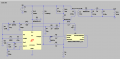
This is LT spice simulation
 

Thread Starter

aman_zman

Joined Jun 4, 2026
6
1780641345017.png

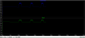
The LT spice simulation is running and giving me around 18v 50w it is between 17-18 and 51-54 and at some intervals a bump could be seen
 

Rf300

Joined Apr 18, 2025
119
The power supply for LT1241 is more than strange. R13 limits the current to about 2 mA (800 V / 400 kOhm). The zener voltage of D4 is specified at 5 mA zener current. What is the supply current of LT1241? The TS will never ever get a stable power supply for the LT1241. Additionally, only 2 mA throgh R13 means already 1.6 W power dissipation in R13.
 

ronsimpson

Joined Oct 7, 2019
4,777
Post your file!
C6 voltage must not drop below 7.6V or the IC will stop oscillating. This problem is common. To test double C6 and see if the "bumps" change in time 2X.
C4 might need a 10K resistor across it. More load.
How did you calculate R9? R9 makes 0.6mA which pulls up Isense to 0.6V more than normal. Isense voltage should not get to 1V. You might be up against 1V limit. Have you tried running at 25W or 10W?

I know you have loop compensation problems. We can look at that later.
 

Ian0

Joined Aug 7, 2020
13,230
I would say that the ratio of L1 to L2 is wrong. The inductance ratio is 67:11, so the voltage ratio is the square root of that 2.5:1, so when producing 18V output, the auxiliary winding will only be producing 40% of that, 7.2V, which will not overcome the UVLO. The unit will keep starting and stopping which what the simulation shows.

I have to wonder about the L3:L2 ratio as well. 450uH to 67uH is a voltage ratio of 2.59:1, so when giving 18V output the flyback voltage on the primary will be only 45V. That's probably OK, but 200V would be more like what I would expect, but it does mean that the peak inverse voltage on the secondary diode will be (800+45)/2.59 or 326V. An MBRS340 won't like 326V! Using a flyback voltage of 200V, by using a voltage ratio of 200:18 will cut that to 90V.

Clock frequency is 1/( 0.583 • RC+ 3.46 •RC/((0.0164)R – 11.73)) which calculates to 643kHz for 12k and 220pF, and that seems awfully high, although the discharge time of 49ns looks like the equation is wrong.
 

ronsimpson

Joined Oct 7, 2019
4,777
Clock frequency is
Agree. 64khz to 120khz is better for this project. The transformer will need more inductance.
the ratio of L1 to L2 is wrong.
That explains why the IC is shutting down. In post #11 I thought the VCC for the IC is too low. I would double the turns or 4x the inductance of L2 which would get you to 15V.
only 45V. That's probably OK, but 200V would be more like what I would expect,
Agree.
 

Thread Starter

aman_zman

Joined Jun 4, 2026
6
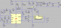
Hi the circuit is running and the output waveform is at 17v 19w with no Bumps and the simulation runs smooth for 100ms
THE ISSUE: Efficiency is very low=39.9% where

Efficiency:
Pout=49.23
Pin=123.622
n=39.9%
This was derived from simulation1781513443240.png
 
Top