Facebook
 Google
 GitHub
 Linkedin
Hi guys
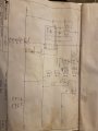
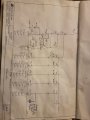
I am having trouble with a safety relay that is giving me a red error light of some kind that i cannot see why. This relay is controlling two door sensors. The lid sensor when lifted gives an error light as it should and then clears when it is closed again. The front door sensor however is not giving an error light when opening but i have taken it off and bench tested it and it is working fine. I just dont know if the relay itself may be giving trouble as it is only controlling these 2 sensors and is being powered by another safety real which is controlling the estops and that too is fine. I have attached info and pics of relay i am using along with sensors and schematic. The error i am getting is on the light beside terminal 24 even though nothing is connected to it.
Terminals 1 and 2 are power and terminal 3 is connected to a NO side of a 3 phase circuit breaker. Terminals 1 and 4 are also linked
link is relay in use
http://www.elobau.com/en/machine-safety/safety-control-units-/-safety-relays/safety-relay-46212.e1.
Attachments
-
![IMG_0402[1].JPG](/data/attachments/127/127206-0ce00bb3728ed42580fedefe3bdb0901.jpg) 205.4 KB Views: 16
205.4 KB Views: 16 -
![IMG_0403[1].JPG](/data/attachments/127/127207-6e342bdc032758c69da8362abdfa89db.jpg) 143.9 KB Views: 16
143.9 KB Views: 16