Problems in choosing an electronic circuit

Thread Starter

mhilmi_w

Joined Jan 8, 2025
7
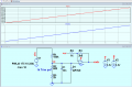
I have a problem, I want to make a voltage sensor that will be seen through the esp32 microcontroller, and the voltage is 175 - 224 V DC from battery 70 cell. What circuit should I make? If I use a voltage divider, how many resistors should I use? and I also want to monitor the current which is approximately 17 A to 20 A using what is the most appropriate circuit? Thank you
 
Last edited:

ericgibbs

Joined Jan 29, 2010
21,391
Hi mhilmi,
Welcome to AAC.
As you may know, the ESP32 ADC will only accept 0V through a +3.3V input voltage.
As you have a ~50V signal variation, based on a 174V voltage, you will require to cancel out the 174V and reduce the 50V signal to 3.3V.
Have you already drawn up a draft circuit method?
E
BTW: I would suggest you check the linearity of the ESP32 ADC section, it has problems

@mhilmi_w
https://forum.arduino.cc/t/fixing-the-non-linear-adc-of-an-esp32/699190
 
Last edited:

Thread Starter

mhilmi_w

Joined Jan 8, 2025
7
Hi mhilmi,
Welcome to AAC.
As you may know, the ESP32 ADC will only accept 0V through a +3.3V input voltage.
As you have a ~50V signal variation, based on a 174V voltage, you will require to cancel out the 174V and reduce the 50V signal to 3.3V.
Have you already drawn up a draft circuit method?
E
BTW: I would suggest you check the linearity of the ESP32 ADC section, it has problems
I originally wanted to monitor the battery voltage using ESP 32 and it uses a voltage divider circuit, but I haven't found the most appropriate circuit because my previous experiment experienced a short when I installed the voltage divider. Is there a good circuit for this?
 

panic mode

Joined Oct 10, 2011
4,866
just note that with those values would require R1 to be at least 2W. or you can increase R1/R2 values tenfold...
also it would not hurt to add some sort of clamping of the input (just in case).
 

ericgibbs

Joined Jan 29, 2010
21,391
hi mih,

If you do not have a +5V supply available, you could use a MCP6001 powered by 3.3V and perhaps limit the output range to 0V through +3V.
As stated, ensure that the divider resistor are correctly power rated or increased in value or use the values in this image.
I would suggest that a 5k Trim pot for the lower resistor, this will enable adjust of the OPA Vout Span.

E
EG57_ 2540.png
 

Thread Starter

mhilmi_w

Joined Jan 8, 2025
7
hi mih,

If you do not have a +5V supply available, you could use a MCP6001 powered by 3.3V and perhaps limit the output range to 0V through +3V.
As stated, ensure that the divider resistor are correctly power rated or increased in value or use the values in this image.
I would suggest that a 5k Trim pot for the lower resistor, this will enable adjust of the OPA Vout Span.

E
View attachment 339935
Thank you very much for your help, after this I will try. Actually I have tried several things using a larger resistor, but maybe the wattage is less so the circuit is shorted which causes the mcb to work for protection. maybe if there are more problems later I will let you know. thank you
 
Top