Problem with thermal runaway in modified AB amplifier

Thread Starter

GeorgeTR

Joined Feb 3, 2018
35
My grandmother recently let me have her Centrex model KH-5511 home stereo system, manufactured sometime in the 1970s. I have taken it upon myself to both repair and modify it to make it better and more suited to my needs. Conveniently, she still had the original user manual, complete with a full circuit diagram (if only consumer electronics still came with those). The stereo was originally only specified to provide 4 watts per channel RMS at 8 ohms. I did some calculations, and figured that by replacing the main power transistors, as well as a few components in the power supply circuit, I would be able to increase this to 20 watts per channel at 4 ohms. The amplifier is a two channel class AB amp.

I ordered what to my knowledge would be the best components for this, and replaced the old ones with these, as well as adding larger heat sinks. Everything seems to function, and it sounds very nice and loud, but I am having problems with thermal runaway. Even with music playing at the lowest audible volume, after about a half hour the temperature of the transistors had reached 60 degrees C, at which point I turned the power off. I glued the biasing diodes to the power transistors with thermal adhesive, similarly to how it had been with the old transistors, so I don't think that a temperature differential between the two is the problem. I am assuming that the problem lies either with the thermal characteristics of the diodes not being compatible with those of the transistors for use in an amplifier, or that the other circuitry that is responsible for biasing was designed specifically for the previous transistors, and needs to be adjusted. However, I may be totally wrong, my knowledge in this area is strictly self-taught.

Either way, I certainly do not have enough knowledge to know how to fix this, regardless of the reason behind it. I was hoping that someone would know of a way to stop this from happening, preferably by replacing components already in the circuit.

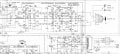
The portion of the circuit diagram describing the amplifier in this stereo is attached. (It also includes a tuner and a tape player/recorder in the same unit.)
The main things I replaced were D1, D2, D3, D4, Q11, Q12, Q13, and Q14. I replaced the diodes with 14N003-T diodes, with this datasheet. Q11 and 12, the NPN transistors, I replaced with TIP41AG transistors, and Q13 and Q14, the PNPs, with TIP42AG. Both have the following datasheet.

Though I am not sure that it is important, I also replaced R63, R64, R65, and R66 with 0.22 ohm 5 watt wirewound resistors, part number 280-CR5-0.22-RC, with these specs. I replaced D7 with part number RS1001M, a 10A bridge rectifier with this datasheet. I replaced C55 with two 15V 14000μF capacitors in series that I bought at a surplus store, in order to reduce the background hum (they were successful in doing so).

Though it is a lower priority, I also noticed that the new transistors seemed to provide much more bass than the previous ones, so that even when the bass was set to zero, it was being significantly boosted from the amount fed into it. I will do some tests to confirm this and find out to what to degree it is happening, but I would appreciate any suggestions as to how to fix that. Like I said, it's a low priority; lots of bass certainly isn't much of a problem, but I would prefer that setting the bass at zero meant the bass actually was at zero.

Thanks in advance!

GeorgeTR
 

Attachments

crutschow

Joined Mar 14, 2008
38,484
I also replaced R63, R64, R65, and R66 with 0.22 ohm 5 watt wirewound resistors
Why did you change their value?
Reducing the value from 0.5Ω to 0.22Ω could certainly contribute to thermal runaway.
I would prefer that setting the bass at zero meant the bass actually was at zero.
Is zero the midpoint of the knob?
If so, that means the bass is unaltered with no reduction or boost, not that the bass is zero.
 

Thread Starter

GeorgeTR

Joined Feb 3, 2018
35
I reduced the value of the resistors so that more current could flow through them for a given wattage. 4.77 amps can flow through these resistors without exceeding their power rating, whereas only 3.16 amps could flow through 0.5 ohm resistors with the same power rating. I guessed that their particular resistance wouldn't matter, but if you think that it might, I will reinstall the old resistors and see if that makes a difference. If that does solve the problem, I think I would want to order 0.5 ohm 10 watt resistors, or maybe just add 0.28 ohm 5 watt resistors (or something close) in series with the resistors I have currently installed.

In regards to your second question, I did mean that the knob was at its midpoint, without any boost or reduction. I now realize that "the bass at zero" could mean that there is no bass at all. What I meant was that when the knob is at its midpoint, meaning there should be neither boost nor reduction, there is in fact a boost. However, this is just my perception, I will want to actually test the amplifier's frequency response to get a definitive answer.

Thanks for the quick and helpful response!

George TR
 
I think I know what's going on. At 4W, you can get away with no bias regulator, so there isn't one.

The voltage across that 0.5 ohm resistor will likely climb at idle.
 

crutschow

Joined Mar 14, 2008
38,484
4.77 amps can flow through these resistors without exceeding their power rating, whereas only 3.16 amps could flow through 0.5 ohm resistors with the same power rating.
20W into a 4Ω speaker is only 2.3A and your average music power is much less than that.
So I see no problem with the original 0.5Ω resistors, which would be dissipating 2.5W maximum and much less on average.
 

Thread Starter

GeorgeTR

Joined Feb 3, 2018
35
I see no problem with the original 0.5Ω resistors, which would be dissipating 2.5W maximum and much less on average.
The original resistors (as shown in the circuit diagram) are only 1 watt, so I will want to order new ones, but you are right that 10 watts would be overkill. I didn't trust my math too much, so I wanted to make sure I had plenty of room for error.

I think I know what's going on. At 4W, you can get away with no bias regulator, so there isn't one.
I am not sure what you mean by this. If there is no bias regulator, than what are the diodes for, and why are they thermally attached to the transistors? Also, why would I still have thermal runaway with the new transistors even if I keep the output far below 4 watts (or even 1 watt)?

The voltage across that 0.5 ohm resistor will likely climb at idle.
Does anyone know how I could prevent this? Also, why is this happening now when it didn't seem to be a problem with the old transistors?

I am not saying that what you said was wrong, I would just like a better explanation. (Like I said, I am not that knowledgeable about this sort of thing).

GeorgeTR
 
I have some issues (a major plumbing problem) to attend to and I can't spend much time right now.

The diodes do provide thermal feedback, but Vbe of the diode and Vbe of the transistor at a given temperature may not be the same. Furthermore, if the Hfe (gain) is not matched then one transistor could be on more than the other.

That;s the way it's supposed to be for class AB.

The voltage across R65 and it's counterpart is an indication of bias current. That's rising uncontrollably.

The difference between the base voltages of Q11 & Q13 is trying to be close to the sum of the B-E drops of Q11 and Q13.

the only thing i can think of is that the gains of (Q11, Q12) and (Q11, Q14) need to be matched respectively.

T9, in this http://bas.elitesecurity.org/proracunPA-eng.html design (the odd transistor) is missing in your amp. It's known as a Vbe multiplier. In a typical design it keeps the difference between the two base voltages of T1/T2 at some value at room temperature and then it changes base don thermal feedback. If the differences of the base voltages are too high, you get thermal runaway. Too low crossover distortion,
 

Thread Starter

GeorgeTR

Joined Feb 3, 2018
35
Thanks for the help and clarification. I think I understand what you mean now. I will try putting R65 and etc. back to 0.5 ohms, and if that doesn't solve the problem, I'll consider something else.

GeorgeTR
 

Thread Starter

GeorgeTR

Joined Feb 3, 2018
35
I re-installed the old 0.5 ohm resistors, and the news so far seems to be good.

With the new resistors, when I turned the stereo on to a barely audible volume, the temperature of the transistors slowly climbed, and eventually leveled off at 44 degrees C, instead of climbing indefinitely as it seemed to do before. (Before I stopped at 60 degrees, so I am not 100% sure it wouldn't have eventually leveled off, but I don't think so.)

I then raised the volume, to what I think was about 1.1 watts per channel. (I'm not quite sure of my math, so I kept it at what I knew wouldn't harm the resistors.) This time, the volume leveled out at 48 degrees.

This seems to have fixed the thermal runaway, at least for these power outputs, but it still doesn't seem quite right. My understanding is that the diodes provide a negative feedback loop that will keep the temperature in check, and perhaps in this situation, the negative feedback doesn't start working properly until this 44 degree point? The old transistors certainly didn't get that hot when they drove a negligible load. Should I be worried about this? Is thermal runaway still a risk, especially at higher volumes?

The way I raised the volume to a point I knew would be safe is I generated a 60 hz tone on my computer, and connected it to the aux input on the stereo. Then I turned up the volume until the voltage on the outputs with no load read 5V with an AC multimeter. I then re-connected the speakers and played music on that same volume. If I had been playing the tone, that would have been 6.25 watts. I could have gone to 5.657 volts (8 watts) before reaching the resistor's ratings, but decided not to to be safe.

However, when I analyzed the volume of the tone compared to the music, the music was 7.54 decibels quieter than the the tone, so that puts the output at only 1.101 watts. If anyone sees a mistake I made, or knows of a better way I should be doing these tests, I would appreciate it if you let me know. Keep in mind I don't have an oscilloscope or frequency/noise generator.

Thanks for the help.

GeorgeTR
 

crutschow

Joined Mar 14, 2008
38,484
My understanding is that the diodes provide a negative feedback loop that will keep the temperature in check, and perhaps in this situation, the negative feedback doesn't start working properly until this 44 degree point? The old transistors certainly didn't get that hot when they drove a negligible load.
The temperature rise with little or no output is determined by the initial bias current in the output stage so, even if the diode temperature feedback is working properly and keeping the bias at a more or less constant value, it still could rise to 44 degrees.
For whatever reason the bias current after the modifications is apparently higher than the original, perhaps due to higher gain in the output transistors.
However, when I analyzed the volume of the tone compared to the music, the music was 7.54 decibels quieter than the the tone.
You music source is likely putting out a lower average voltage than your signal source.
a better way I should be doing these tests
The best is just to turn on some music you typically listen to at the loudest listening level you are ever likely to use, and see how much the transistor temperature rises.
 

Thread Starter

GeorgeTR

Joined Feb 3, 2018
35
Thanks for the reply!

I checked the datasheets for the two transistors, and it seems hard to say if one has higher gain in general than the other, but the curves of the graphs related to temperature and current are slightly different shapes, so it seems perfectly possible that that could be the reason.

Since it seems there's no reason to worry about the 44 degrees, I'm not going to. If I ever have problems with temperature rise, I should be able to put on larger heat sinks.

I do agree that your methed for doing tests is the best, but I don't have the stereo arranged the way it's eventually going to be, and I'm not sure exactly how big the room I'm going to put it in is, so the loudest I need it to be is hard to say. My main concern in this test was preventing harm to the resistors, but that shouldn't be a problem in the future.

Next I want to test the frequency response to see if the bass circuit needs adjusting, and to generally see how level it is. I'll make sure to post my results and explain how I did it when I'm done.

I'm very glad that this problem was easily fixed. I was worried I would have to abandon the idea and settle for 4 watts.

GeorgeTR
 

Thread Starter

GeorgeTR

Joined Feb 3, 2018
35
Thanks for the correction.

I will probably still order some 0.5 ohm 2 watt resistors eventually, especially since these resistors are 40 years old, but I'll make it a much lower priority. All four would be less than a dollar, so I don't see why I shouldn't do it, but I'll probably wait until I have something else to order with them.

George TR
 

Thread Starter

GeorgeTR

Joined Feb 3, 2018
35
I tested the frequency response of the stereo, and the results are in the attached document.

First, I generated sine wave frequencies spanning the entire audio spectrum using my computer. Then I used an auto-ranging digital multimeter I have set to AC volts and measured the volts coming directly out of the computer using it. I did this to try to calibrate for the multimeter giving different measurements at different frequencies.

Then I hooked my computer to the stereo and tested the voltage coming out of the stereo without load for those same frequencies. I arbitrarily set the value at 640 Hz to 0dBs, and compared all the other frequencies to it. The results seem fairly good. I am fairly sure that the strange peak at about 7kHz is due to inaccuracy in the meter, especially since this article shows the frequency response of multimeters changing depending on which range they are in.

Unlike what I suspected, there was not a boost in bass. The reason I thought there was I think has to do with the speakers I've been using. They're 4 ohms, and when I tested them first with a different stereo, and then used them with this one before the new transistors, they had a quite low amount of bass, so I had to turn the bass up a lot to make them sound nice. I assumed this was due to their crossover, as well as them possibly being designed to be used with a subwoofer. However, with these new transistors, they have a perfectly good amount of bass. I suspected this was because the bass was being boosted. Now I think that it was because both of times I previously tested the speakers, I was using stereos designed for 8 ohms. I have seen in various places that mismatched impedance can lead to an undesirable change in tone. I now believe that this was the reason for the low amount of bass, and now that these new transistors can supply all of the current that the speakers will ever need, there tone is back to how it should be.

I hope you find this interesting.
 

Attachments

Audioguru

Joined Dec 20, 2007
11,248
The original temperature compensating diodes were probably small like a 1N4148 and matched the low current base-emitter junctions of the output transistors. But you wrongly changed the little diodes for high current rectifiers that are completely different to a base-emitter junctions. Use 1N4148 little diodes, not 1N4003 high current rectifiers.

The 470uF output capacitors will have a -3dB cutoff frequency of 85Hz so the bass will not be good.
 

crutschow

Joined Mar 14, 2008
38,484
Then I hooked my computer to the stereo and tested the voltage coming out of the stereo without load for those same frequencies
For a proper test you should test with the speakers or a 4 ohm resistive load connected.
For example you won't see the bass rolloff that AG mentioned with no output load.
 

Thread Starter

GeorgeTR

Joined Feb 3, 2018
35
Thanks for the suggestions.
For a proper test you should test with the speakers or a 4 ohm resistive load connected.
I will try to do the test again with a load. Part of the reson I was hesitant to do so is that I know speaker impedence can vary with frequency, and that would affect the results. I will try again find something I can use as a resistive load, or try it with the speakers anyway.
The 470uF output capacitors will have a -3dB cutoff frequency of 85Hz so the bass will not be good.
I will see what the numbers say, but I certainly haven't noticed anything while listening. Do you know the purpose of these capacitors? Were they there to prevent harm to the (cheap) speakers originally provided with the stereo? What about the 0.1μF capcitors?

If I do notice a rolloff in bass and decide to fix it, would it be best to just bypass the capicitors? Or should I change their value to one that would result in a frequency more like 20Hz? If so, what value might that be? (I could try to figure that out, but I still don't trust myself with the math.)
The original temperature compensating diodes were probably small like a 1N4148 and matched the low current base-emitter junctions of the output transistors. But you wrongly changed the little diodes for high current rectifiers that are completely different to a base-emitter junctions. Use 1N4148 little diodes, not 1N4003 high current rectifiers.
I had to replace the original diodes because they were glued to the original transistors, but I had no idea of their specs. The circuit diagram only supplied a cryptic "MV-1". So I guessed and used the diodes that were most easily available. It is nice to know which ones I probably should have been using, and with luck that might fix the strange 24° temperature rise under negligible load.

Thanks for the help!
 

crutschow

Joined Mar 14, 2008
38,484
Do you know the purpose of these capacitors?
To block the DC from burning out the speakers. The DC at that point is about 1/2 the supply voltage.
What about the 0.1μF capcitors?
They are to roll off the high frequency response and prevent oscillations due to the inductive increase in speaker impedance at high frequencies..
If I do notice a rolloff in bass and decide to fix it, would it be best to just bypass the capicitors? Or should I change their value to one that would result in a frequency more like 20Hz? If so, what value might that be?
Obviously you don't want to bypass them. Components are seldom put in a circuit without a good reason.

For a 20Hz corner frequency with a 4 ohm speaker C = 1/(2pi*20*4) = 2,000μF.
It is nice to know which ones I probably should have been using, and with luck that might fix the strange 24° temperature rise under negligible load.
I'd be surprised if they help since smaller diodes will have a higher impedance and will tend to increase the output bias current, not reduce it.
 

Thread Starter

GeorgeTR

Joined Feb 3, 2018
35
I'd be surprised if they help since smaller diodes will have a higher impedance and will tend to increase the output bias current, not reduce it.
Are you disagreeing with Audioguru?

If using smaller diodes won't help with that problem, then why would I want to install them? Are you saying I shouldn't install them?

If you're saying it doesn't really matter, then I would prefer to leave things the way they are, especially since I know that it works right now.
 
Top