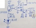
Problem with current sense circuit using opamp

Thread Starter

Vilius_Zalenas

Joined Jul 24, 2022
173
Could you post of few details of what the actual problem ended up being and how you solved it.
I changed my op amp to OP290 (I guess it is rail to rail one). I went for the low side sensing. I changed all four resistor values to 100k (resulting in the gain of one). Then I used the second op amp on the same chip with a gain of 92 (9.1k and 100 ohm resistors) in a non inverting configuration to amplify the signal to to almost full 0-5 V range.


However, there is one last consideration. This current sense circuit will be used to measure, how much current LNA is drawing. I will be using the Bias Tee to provide the DC voltage to the LNA, but how about the current measurement on the low side this time? Should I connect it in this way and expect to get accurate measurements, I am just not sure about the RF component in it...? (Picture in the attachments)
 

Attachments

BobTPH

Joined Jun 5, 2013
8,996
U am still trying to figure out how amplifying a current to voltage conversion meets this specification:
The device should have only 3 states: Current is lower than 10 mA Current is between 10 and 100 mA Current is higher than 100 mA
 

Thread Starter

Vilius_Zalenas

Joined Jul 24, 2022
173
U am still trying to figure out how amplifying a current to voltage conversion meets this specification:
I was telling, that I am only interested in the voltage region that depicts the current of 10-100mA. I don not need very high accuracy, I am not going to do any ADC type measurements. Beside this op amp, there will be 2 comparators checking the condition (if the current is lower than 10 mA or higher than 100 mA)
 

Alec_t

Joined Sep 17, 2013
14,329
how about the current measurement on the low side this time? Should I connect it in this way and expect to get accurate measurements, I am just not sure about the RF component in it...? (Picture in the attachments)
Should be ok. Your chosen op-amp has a unity-gain bandwidth of only 20kHz, so is unlikely to have any significant RF component in the output. Any slight ripple in the output could be suppressed with a low-pass filter or else ignored.
 

Irving

Joined Jan 30, 2016
3,894
However, there is one last consideration. This current sense circuit will be used to measure, how much current LNA is drawing. I will be using the Bias Tee to provide the DC voltage to the LNA, but how about the current measurement on the low side this time? Should I connect it in this way and expect to get accurate measurements, I am just not sure about the RF component in it...? (Picture in the attachments)
As said,the opamp probably won't notice the RF but it could potentially cause instability. I'd put a capacitor from the SMA outer pin to the ground plane such that Zc is << 0.5ohm at the frequencies in use.
 

Thread Starter

Vilius_Zalenas

Joined Jul 24, 2022
173
As said,the opamp probably won't notice the RF but it could potentially cause instability. I'd put a capacitor from the SMA outer pin to the ground plane such that Zc is << 0.5ohm at the frequencies in use.
If I understand you correct, you would eliminate my 50 ohm resistor in the Bias Tee RF branch, and just leave a pF order capacitor (in the same RF branch) to short the RF to ground? Is that right?

One more question to consider in the future. I have not noticed any difference between connecting a 5-10k load resistor at the op amp`s output and leaving the output without any load. Does a load resistor (of a reasonable value) affect the op amp in any way?
 

Irving

Joined Jan 30, 2016
3,894
If I understand you correct, you would eliminate my 50 ohm resistor in the Bias Tee RF branch, and just leave a pF order capacitor (in the same RF branch) to short the RF to ground? Is that right?
No, see pic. The 50ohm load isn't needed, it will just reduce the input signal to the next stage, assuming that has a 50ohm input impedance.

1677519351073.png


One more question to consider in the future. I have not noticed any difference between connecting a 5-10k load resistor at the op amp`s output and leaving the output without any load. Does a load resistor (of a reasonable value) affect the op amp in any way?
The output impedance of an opamp is low, a few 10s of ohms, so a load resistor has little effect.
 

Thread Starter

Vilius_Zalenas

Joined Jul 24, 2022
173
No, see pic. The 50ohm load isn't needed, it will just reduce the input signal to the next stage, assuming that has a 50ohm input impedance.

View attachment 288527


The output impedance of an op amp is low, a few 10s of ohms, so a load resistor has little effect.
Sorry if I look so stupid and unexperienced for you, but in that case I have another question. The LNA is for a precision GPS antenna operating in around 1.5 Ghz, typically it draws around 66 mA.

My idea behind a 50 Ohm resistor was that I wanted to dissipate all the signal (content of the signal itself has no role in this task) on that resistor thus matching the impedance. If I removed the resistor, wouldn`t I get terrible reflections causing untrue current consumption? I did not quite understand your circuit edit (were there 2 capacitors, or was it ground?.) Could you redraw the circuit for me from zero? I really appreciate your time and help. I am very grateful to you.
 

Thread Starter

Vilius_Zalenas

Joined Jul 24, 2022
173
I encounter another problem. After the signal is amplified, I supply it to the comparator (LM393). If the signal is lower than 0.45V the blue led should light up. However, the LED does not light up unless I touch the output of the comparator with my finger, or a multimeter lead. Is it possible that the LM393 could not source as much current to fully turn on the transistor? If so, how would you solve this problem, what is the easiest way? I made sure I am getting my signal on the right pins, wiring is correct.
 

Attachments

sarahMCML

Joined May 11, 2019
370
I encounter another problem. After the signal is amplified, I supply it to the comparator (LM393). If the signal is lower than 0.45V the blue led should light up. However, the LED does not light up unless I touch the output of the comparator with my finger, or a multimeter lead. Is it possible that the LM393 could not source as much current to fully turn on the transistor? If so, how would you solve this problem, what is the easiest way? I made sure I am getting my signal on the right pins, wiring is correct.
You need a pull-up resistor on the output of the LM393, they are open collector!
Why don't you just swap your inputs and put your LED and resistor in the output of the comparator, and get rid of the transistor?
 

Thread Starter

Vilius_Zalenas

Joined Jul 24, 2022
173
You need a pull-up resistor on the output of the LM393, they are open collector!
Why don't you just swap your inputs and put your LED and resistor in the output of the comparator, and get rid of the transistor?
The led needs 20 mA, ant the resistor is calculated to make around 1.3 V drop. Would lm393 output steady 5V @ 20mA?? I havent tried, but I guess thats too much of a task for a comparator...
 

sarahMCML

Joined May 11, 2019
370
The led needs 20 mA, ant the resistor is calculated to make around 1.3 V drop. Would lm393 output steady 5V @ 20mA?? I havent tried, but I guess thats too much of a task for a comparator...
Does your LED really need 20mA? Try it with maybe 150 Ohms. A modern one should be more than bright enough.
 

Juhahoo

Joined Jun 3, 2019
302
Are you forced to use an op amp in this circuit?, check INA240, it has built in amp and adjustable ref voltage so you can measure bidirectional currents.
 
Top