Certainly it is some kind of amplifier, although I see nothing indicating the input or output in the first post. AND the presentation is indeed non-conventional.
Certainly it is some kind of amplifier, although I see nothing indicating the input or output in the first post. AND the presentation is indeed non-conventional.
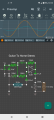
Substitute the signal generator with a guitar. The resistor that is labeled ZL and 10K is not an actual part in the circuit. ZL and 10K refer to the load impedence, placed on the output of the op amp.
I see nothing wrong with the circuit. It should function and provide gain. The gain will be quite high, but with a 9 volt battery and the input biasing, the stereo system will be the first section to produce distortion, well before this circuit starts clipping.
The circuit is a variation of the classic single supply non inverting amplifier.
For use as a guitar adapter the Twill need to provide shielding and adequate ground integrity.
 Facebook
 Google
 GitHub
 Linkedin
 226.7 KB Views: 51


