Facebook
 Google
 GitHub
 Linkedin
Hello.
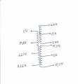
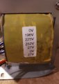
I bought today a transformer which was used in an UPS. I do not know the power of this transformer, all I know is that is has 2 high current windings of 15.5V, 2 low current of 27V, and 3 windings for 230V connections marked with 0V, 196V, 225V, 252V. The person said that the transformer was taken from a new UPS which had a problem at the PCB.
The problem is that the person from which I bought the transformer has inverted the label on the primary side of the transformer and the 0V standed for 27V and I connected the 230Vac mains to 27V and 0V. After this, I plugged the power cord and nothing happened, but after this I plugged the cord the second time and some smoke comed up from the transformer and I saw some sparks.
A few hours later, I managed to find the problem and I powered correctly the transformer. Now the transformer works good, but I checked with load only the primary and de 15.5V secondary. The 27V secondaries were only measured and they are approximately 27Vac each.
Are there any problems that can appear, for example after this error could the isolation between the primary and secondary to be affected ?
I am very sorry and I feel very bad for happening this things but I did not knew that the label was inverted.
Attachments
-
 94.7 KB Views: 14
Last edited: