power supply

Thread Starter

benjji

Joined Sep 9, 2022
7
Hello
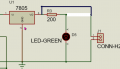
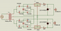
I am relatively new to electronics and i am trying to design an isolated full wave bridge rectifier circuit. i am using a center tapped transformer with an output of 12V and 300mA. I am using a single transformer to power 2 of the rectification circuits. The voltage at the output is ok, however the current is less than20mA. please how can i get a current of atleast 200mA. the circuit is shown below
 

Attachments

MrChips

Joined Oct 2, 2009
34,810
Welcome to AAC!

There are a number of issues with your schematic diagram.

1662732038003.png

First of all, what do you mean by "isolated"?
Your schematic shows two power supplies, +5V and +9V. They are not isolated from each other.
What voltages do you actually need to create?

U1 and U2 voltage regulators are missing output capacitors (about 1-10μF) to prevent oscillation.
Resistors R1 and R3 are in the wrong place. The should be in series with the LEDs and not with the output of the regulators.
R1 and R3 values should be increased. (There is no R2. You should change R3 to R1, and R1 to R2.)

Edit: In other words, J1 and J2 are connected to the wrong nodes. (Eric beat me to it.)
 

wraujr

Joined Jun 28, 2022
259
First, your resistors (R1 and R3) are in the output path limiting output current. Outputs of regulators go straight to output pins and R1/R3 are simply in line with the LED only.
Second, you need to read datasheets on those regulators for their "sample" designs. You are missing some suggested capacitors.
 

dl324

Joined Mar 30, 2015
18,326
Welcome to AAC!
i am trying to design an isolated full wave bridge rectifier circuit.
What do you mean by isolated?
the circuit is shown below
Since you're new, it would be beneficial for you to learn how to draw schematics properly.
  1. The 9V regulator is drawn upside down. In that configuration, we would assume that it was for a negative voltage.
  2. You shouldn't draw wires over text.
  3. You should put appropriate space between symbols so they don't touch (or look like it), e.g. the two ground symbols.
  4. Ground should always point down. This will avoid confusion with some symbols for positive voltages.
  5. We usually put the filter cap between the rectifier and regulator.
From the 1980 National Semiconductor Voltage Regulator Handbook:
1662734299483.png

It was nice that you drew the circuits with some symmetry. Many schematics by newbies look awful.

As noted, you shouldn't have resistors in series with the outputs. That defeats the purpose of using voltage regulators.
 
Last edited:

ericgibbs

Joined Jan 29, 2010
21,442
The voltage at the output is ok, however the current is less than20mA. please how can i get a current of at least 200mA. the circuit is shown below
Hi,
The TS asked a simple, direct question.
The simple answer, wrong Vout take off point.

Why do we feel it is necessary to criticize his drawing technique when he has not asked for any input regarding his drawing layout.?

E
 

dl324

Joined Mar 30, 2015
18,326
Why do we feel it is necessary to criticize his drawing technique when he has not asked for any input regarding his drawing layout.?
He is inexperienced and doesn't know good technique from bad. Letting him unknowingly develop bad habits is not doing him any favors.
 

Jon Chandler

Joined Jun 12, 2008
1,596
If the two points with ground symbols are connected together, D3 and D8 are connected in parallel. I think that's going to create problems.

It's probably better to use a single bridge rectifier and filter cap, and run the two regulators from there.
 

crutschow

Joined Mar 14, 2008
38,506
Here's a circuit that may be of interest, which gives two positive output voltages from a center-tapped transformer using one bridge rectifier, with one output being ≈1/2 the voltage of the other.
That way there is less dissipation in the lower voltage regulator.

It provides two voltages by having the higher voltage generated by all the diodes acting as a full-wave bridge from the two outer transformer terminals, and the lower voltage by the two bottom diodes acting as full-wave rectifier from the center-tap.

Interestingly, current from either output load generates balanced currents in the two halves of the transformer secondary.

1662745075081.png
 

Thread Starter

benjji

Joined Sep 9, 2022
7
Welcome to AAC!

There are a number of issues with your schematic diagram.

View attachment 275890

First of all, what do you mean by "isolated"?
Your schematic shows two power supplies, +5V and +9V. They are not isolated from each other.
What voltages do you actually need to create?

U1 and U2 voltage regulators are missing output capacitors (about 1-10μF) to prevent oscillation.
Resistors R1 and R3 are in the wrong place. The should be in series with the LEDs and not with the output of the regulators.
R1 and R3 values should be increased. (There is no R2. You should change R3 to R1, and R1 to R2.)

Edit: In other words, J1 and J2 are connected to the wrong nodes. (Eric beat me to it.)
The little research i did showed that a rectification circuit with a transformer is isolated and the one without a transformer is non isolated.

please your inputs and advice are very much appreciated. thank you very much
 

Thread Starter

benjji

Joined Sep 9, 2022
7
First, your resistors (R1 and R3) are in the output path limiting output current. Outputs of regulators go straight to output pins and R1/R3 are simply in line with the LED only.
Second, you need to read datasheets on those regulators for their "sample" designs. You are missing some suggested capacitors.
I will do so. I am very grateful for the help
 

Thread Starter

benjji

Joined Sep 9, 2022
7
If the two points with ground symbols are connected together, D3 and D8 are connected in parallel. I think that's going to create problems.

It's probably better to use a single bridge rectifier and filter cap, and run the two regulators from there.
that is very interesting. I will try that out
thank you very much.
 

Thread Starter

benjji

Joined Sep 9, 2022
7
hi,
Checking that tran-2P3s, it is shown as a Proteus transformer symbol.?

I think all his circuit shows is a simulation .???
E
Please yes, i designed with Proteus, tested for voltage and constructed it. however after construction, it was not able to power an arduino board so i checked for current and noticed the current was too low
 

Thread Starter

benjji

Joined Sep 9, 2022
7
Here's a circuit that may be of interest, which gives two positive output voltages from a center-tapped transformer using one bridge rectifier, with one output being ≈1/2 the voltage of the other.
That way there is less dissipation in the lower voltage regulator.

It provides two voltages by having the higher voltage generated by all the diodes acting as a full-wave bridge from the two outer transformer terminals, and the lower voltage by the two bottom diodes acting as full-wave rectifier from the center-tap.

Interestingly, current from either output load generates balanced currents in the two halves of the transformer secondary.

View attachment 275908
I appreciate the help very much sir. I will try my hands on the circuit. i am grateful
 

wraujr

Joined Jun 28, 2022
259
One quick step back:

Is your goal to generate one +5VDC and one +9VDC output?

If so you only need one set of bridge rectification (D1-D4) and one filter cap (C3)
Also, you would not use the center tap of the transformer (leave unconnected).
Connect bridge rectifiers to transformer "pins" 3 and 5.
Connect output at filter cap to both regulator inputs.

BUT this assumes your transformer is a 12V center-tapped and the pins 3/5 give you 12VAC into rectifiers.
This gives 12VDC (approx) out of filter cap into the 5V and 9V linear regulator (3V above 9V is required)

Now if your transformer is 24VAC then using pins 3/5 will give 24VDC into regulators and they will dissipate
a large amount of heat depending on current load. So if you already have transformer, you would
ground the center-tap and then use two sets of bridge rectifiers and filter caps, one set feeding each regulator.
 
Top