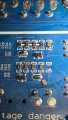
Identifying potential missing resistor on a WSP3010H 30V 10A Bench Power Supply

Thread Starter

5VSB

Joined Nov 15, 2024
2
Hi,

I'm in the process of trying to repair my NANKADF WSP3010H 30V 10A Bench Power Supply. I've replaced the damaged components and ordered some other parts for it. However, there is what looks like a missing resistor near the TL494C IC.
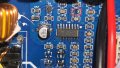
Picture_20260604074948.jpg

I've marked the potential missing resistor (R50) on the board. Q3 and Q4 I know about (they're one of the parts I had to order).

I've tried to look online and can't find out what the value of the resistor could be. I did see some YouTube videos showing a similar board and there was a resistor there, but they did not zoom in enough.

Does anyone happen to have a power supply like this one and can look to see if R50 is populated and if so, what the value of the resistor is? It'd be greatly appreciated.
 

ci139

Joined Jul 11, 2016
2,017
? Q4 Q3 pads are unpopulated also . . . ? might be a manufacturer mod insted of suspected bath-flow or thermal drop off
 

Irving

Joined Jan 30, 2016
5,195
R50 is part of the voltage control feedback loop. It's impossible to say what value it should be without reference to the other resistors in that loop. It clearly was populated as there are clear signs that the solder on the pads has cracked off. It's unlikely that part overheated given the current through it would be a few 100 microamps at most - unless there was some other catastrophic failure within the TL494 that connected a high voltage to that pin internally.

Did you try searching for a user or service manual for the PSU? These Chinese products often use the same venerable designs that can be found across several manufacturers so worth looking for service manuals for similar products.
 

Thread Starter

5VSB

Joined Nov 15, 2024
2
Well this PSU has failed twice so far. The 1st failure was while I was testing an ATX AM4 desktop motherboard I had just repaired. It was booting into Windows and current spiked to near 10a (voltage was set to 12V). As it spiked, the PSU went bang.

I found a blown F5AL250V fuse and 2 shorted K3569 MOSFETs. The fuse was badly burnt and damaged. The fuse was replaced with another F5AL250V and the K3569 MOSFETs were replaced with ones I got off Aliexpress.

I connected it to my dim bulb tester and it was fine. It then continued to work without problems for about a month. The 2nd time it was in use while testing another AM4 motherboard. It was just sitting idling in the BIOS at 12V with around 5.5A current draw. All of a sudden, the PSU went bang again and this time tripped the RCD for the power sockets. I also saw a blue flash at the back of the PSU.

Checked fuse again and this time it had not blown. No visible damage and it still had continuity. Opened PSU again to check for damage and nothing obvious on front side. At the back of the board, there was a visible burn marks and several damaged components (several resistors, 2 diodes and 2 BA SOT23's). These were under the large transformer. I cleaned this area and replaced all damaged components.

This was the damaged area under the transformer (burn marks were cleaned with IPA):

Picture_20260531012103.jpg

I also found this time one of the K3569 MOSFETs had shorted, but the other one wasn't reading a short. I replaced both of these again anyway.

After doing this and ensuring nothing else was shorted/visibly damaged, I connected the PSU to my dim bulb tester again. It came on but the bulb and display on the unit was flickering constantly. I saw some smoke coming out so I quickly turned it off.

I couldn't figure out where the smoke was coming from, so to try and figure it out, I got my thermal camera out and quickly powered it on via the tester to see if that showed anything. It did. It showed major heat spots around the Q3/Q4 area. I looked at that area under a microscope and saw Q3/Q4 had visible burn marks on them - likely what let out the smoke. So I desoldered them which is why Q3/Q4 is currently not populated.

Q3/Q4 weren't visibly damaged beforehand. I took a picture of the area after the 2nd failure. Q3/Q4 are SOT23's with "HF" markings. I've ordered these online and waiting for them to arrive. I've also ordered new TL494C chips just in case. The BA SOT23's that are right under Q3/Q4 have also been replaced. I had some spares from a pack I bought before.

Currently the PSU turns on and stays on with no smoke, but doesn't work properly when pressing the output button (which actually turns the PSU on and allows you to provide voltage to whatever you need it to) due to the issues around the TL494C area.

I noticed the missing R50 resistor a while ago. I don't know if the 1st or 2nd failure blew this resistor off. It certainly looks like it just vanished. What's weird is why it's only that one and none of the others.

I haven't looked at the manuals yet. I will look into that, but easiest would be finding someone that has this PSU or similar and can look at their board to see what numbers are printed on the resistor. Probably won't find the value of it otherwise which would be a shame.

I know from the sounds of this, it probably isn't worth trying to repair, but I'd like to try and get it working. It's a fun little project.
 
Top