Help identifying pcb component

Thread Starter

soundcomputer

Joined Jul 6, 2026
7
Hey there!

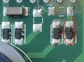
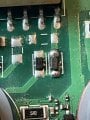
Can someone help me ID what appears to be a burned out diode? There are good ones beside it for comparison. The neighbours have B2 W72 and 5 lines written on them.
It’s from a lowrance gps/depth sounder that I’d like to repair.
Thanks!!
 

Attachments

Irving

Joined Jan 30, 2016
5,195
Welcome to AAC.

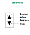
Most likely is a 58v transient voltage suppressor diode (TVS) PTVS58VS1UR (manufactured by NXP) or similar

Can you confirm physical dimensions.

Given that level of damage there maybe other failed parts.
 

Thread Starter

soundcomputer

Joined Jul 6, 2026
7
Without having calipers, I can only tell that it's about 2x1.5mm.

A search with google images points towards a zener BZT52-B20, but I'd like humanoid opinions :)
 

Irving

Joined Jan 30, 2016
5,195
In that location, looking at how they are arranged and connected to ground and a supply rail, a fast TVS diode is much more likely than a Zener diode.

That diode serves to protect an input to the PCB, it has no involvement in the device functionality. So the overall device should still function ok without replacing it. If it doesn't then, as I said previously, there's likely to be significant further unseen damage.

That's a 400W rated part, it takes a fair amount of electricity to fry it. Do you know the circumstances that destroyed it?
 

Thread Starter

soundcomputer

Joined Jul 6, 2026
7
No, couldn't say what caused it.

It's from a Lowrance gps plotter / depth sounder on my boat which was working fine and then it suddenly stopped reading depth properly. I went through all settings and it barely reads depth in the shallows. At first I suspected the transducer, but a friend's device worked just fine with it. All other functions still work.

The device is about 10 years old and the boat is in the water year round (I'm on the west coast of BC, Canada). Maybe it didn't like the cold...

Anyway, I'd like to find a replacement diode and give it try before I spend the money on a new unit.
 

Irving

Joined Jan 30, 2016
5,195
Hmmm... carefully remove the broken part, just in case its affecting the signalling on that circuit. If the sounder works OK with that removed then you're lucky and can just replace it. If however the fault persists then I'm afraid there is other damage you cannot see.

The broken part is passive; it plays no part in the operation of the sounder, its there to protect the rest of the circuit in the event of a voltage spike on that input - eg from a static discharge, an accidental brief short, eg to a +ve battery voltage, or a induced voltage, eg from a nearby lightening strike. The scale of the damage it has sustained tells me it has been either overloaded for a significant time or by a lot of energy, which suggests #2 as most likely, or an extremely close #3.

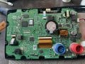
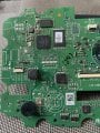
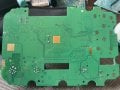
If you post a wider photo (hi res and in focus) from directly above of the whole board I may be able to suggest further action you could take.
 
Last edited:

panic mode

Joined Oct 10, 2011
5,099
check the silkscreen. they are possibly regular diodes. they are connected in antiparallel do it would not matter if they are Zener or rectifiers.
 

Irving

Joined Jan 30, 2016
5,195
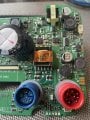
Hmm, I guessed as much, so I would hazard a guess (based on a little experience of such things) that you have a ground/screen connection, 2 pins for the sender, and 2 for the receiver. I suspect the other 2 pins are power for a different sort of transducer. It looks like those circuits come from the output transformer, so they are more likely the high-power output... so my original premise may be wrong.
 

Irving

Joined Jan 30, 2016
5,195
I think these diodes act as a switch. When the transmitter is running the voltage generated to drive the piezo element overcomes the diode forward voltage. On receive the transmitter is turned off and the piezo element acts as a microphone but the voltage generated is only millivolts so is blocked by the diodes and is steered to the receive chain. There must be some switched input protection on the receive chain to avoid damage from the transmitter, which may have been compromised by the fault.

Since the TS reports the unit is 'working but deaf', either the transmit output is compromised by the blown diode or, more likely, the receive input has suffered. The only way to tell will be to look at the TX and RX signals with a 'scope. Replacing the dead diode with a good one may restore the system, but I suspect not.
 
Top