 Facebook
 Google
 GitHub
 Linkedin

Hi, I’m just curious if anyone might be able to explain a possible over-heating issue with a mosfet/circuit, I designed the above circuit myself? I don’t have much hands on experience using mosfets, but I know how to work with them well enough to design my own decent circuits with them.... I have plenty of experience with bjts on the other hand, whether NPN or PNP I use them just as often as the other.
Alright, so the issue I’m having is the Mosfet heats up and feels like it just gets hotter and hotter gradually but over a short time, can probably only keep the power on for for up to maybe 15 seconds before it gets much too hot to touch. I’m not using a heat sink cause I don’t have one. I have tried adding another mosfet in parallel, but it still gets just as hot (however only one of them gets super hot -(the extra one), while the other doesn’t even seem warm). I’m honestly not sure why it’s heating up so easily if the datasheets say it can handle 49 Amps continuous and dissipate up to 94 or 95 Watt... The mosfet in this circuit is only dealing with near 1 Amp, and dissipating about 5.15 watts across the Drain-Source region. So honestly I’m kinda clueless as to why it’s happening or what I can do to fix it without getting into pwm.
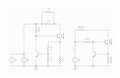
Here’s Some more Info about the circuit above:
it’s supposed to function as a current limiter (not to be confused with current source). The circuit on the left side is the actual breadboard prototype, and the one on the right is the equivalent circuit. The Mosfet I’m using is (IRFZ44N) and the bjt I’m using is (2N3904). Theleft circuit some of you make wonder why I used so many resistors or 2 batteries in parallel... I did that just to obtain precise resistance values and to take care not to exceed their power ratings so they don’t over heat. As for the batteries, I put two energizer 9v batteries in parallel because they can’t handle much current by themselves.... but even with two of them the overall supply voltage still drops to about 5.3v while in use (but that’s a lot better than about 2.4v with just one).
My intended calculated current limit for this circuit is about 900mA (0.61/0.6666... =0.9), however I’ve measured an actual current limit of about 850mA while under test, so that’s a +/-50mA... not too awful bad whith a current so high and a very unreliable power source.
Just for the extra info.... The Bjt, (over a very wide range of testing with different shunt resistors and Loads *including a short as a load*) has proved to hold a pretty constant max of a 0.6-0.61 volt Vbe drop even at almost 1Amp, so I know my designed circuit actually functions pretty well including given that I’ve also tested the load current with every various intended current limits, it’s usually had an accuracy of about +/- 0.0005A (500uA) unless the current is really high, which is not bad I would think considering it’s simplicity.
Please let me know what you guys think, I’m not sure where to go from here yet, I’m a little stuck right now.
If I can get this circuit to function without overheating anymore then I eventually plan to use it as a high power driving circuit, pulsed with a 1% duty cycle @ 1 Amp for an IR emitter I have
Attachments
-
 67.6 KB Views: 4


