I would love it! The more detail, the better. For example, what are the important properties of the transistors chosen—i.e., why did the designer choose them instead of others. Thanks for your time already on this!
The circuit is OLD! I used similar circuits and BC549 transistors 50 years ago.
The datasheet of the BC549 transistor tells you that it has low noise for use in audio equipment.
The circuit is not hifi because it has no AC negative feedback and will produce distortion.
It is powered from the electret mic input of a mixer or audio amplifier. I think it will not be powered properly.
You said you have an electric guitar and will feed it to this preamp circuit.
But an electric guitar uses a high level, high impedance pickup. This preamp is designed for a low level, low impedance dynamic microphone which are completely different.
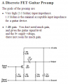
A magnetic guitar pickup is usually fed to a low gain high input impedance vacuum tube or Jfet. then the tube or Jfet output is line level, not microphone level. Here is a typical circuit that a guitar pickup feeds:
The signal output is on T.
R is used to supply power to the preamp.
S is both power return and signal ground.
Most guitar pickups are passive transducers that are fitted to bass/treble/volume controls as well as mechanical switches to select pickup #1, #2 or both #1 and #2 for tonal control. The signal is fed via 1/4" phone jacks and cable.
If one wanted to add a preamplifier to the guitar, then it would make sense to locate the preamp as close as possible to the pickups, i.e. in the guitar body. In order to do this, one has to supply power. It is customary to supply power via a PP3 9V battery installed in the guitar body. The alternative is to supply the power via the instrument cable, sometimes called "phantom power" on mixer boards.
Hence in this circuit 5-12V power is likely to come from the unit that the preamp is plugged into via the TRS plug.
C7, 10μF, 16V is a power supply smoothing capacitor. This is not an option.
It helps to keep the supply voltage steady. Typical value is 10-47μF. You might think, "why not put a large value capacitor?" A higher value would give better smoothing. This is where paying attention to capacitance ESR is important (Equivalent Series Resistance). In order to manufacture capacitors with high capacitances, physical dimensions increase, hence ESR also. Hence there is a trade off. At higher capacitance, higher ESR means that the capacitor is less effective at removing high frequencies. Hence if you want to attenuate HF noise in the power rails you have to use capacitors with low ESR.
While tantalum capacitors have lower ESR, in this application, aluminum capacitors will work fine.
 Facebook
 Google
 GitHub
 Linkedin
") For example, what are the important properties of the transistors chosen—i.e., why did the designer choose them instead of others. Thanks for your time already on this!
For example, what are the important properties of the transistors chosen—i.e., why did the designer choose them instead of others. Thanks for your time already on this!