MPRLS0300YG00001B pressure sensor failing after repeated BP tests – possible cause?

Thread Starter

Abhimanyu P

Joined Jan 9, 2026
5
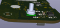
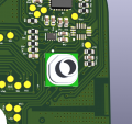
I am using the MPRLS0300YG00001B pressure sensor on my custom PCB for a blood pressure measurement application.

Initially, the sensor works very well, and the readings are accurate. However, after 7–8 test cycles, the sensor stops responding completely. I have already lost more than 10 sensors with the same issue.
I would like to understand:

  1. What could cause this sensor to fail after repeated pressure tests?
  2. Could this be due to over-pressure, pressure spikes, moisture, condensation, or cleaning procedures?
  3. Are there any recommended protection methods (pressure limiting, filters, venting, isolation) for BP applications?
  4. For blood pressure measurement, is an analog pressure sensor or a digital pressure sensor generally more reliable?
  5. Can anyone recommend a pressure sensor suitable for non-invasive blood pressure applications?

Any insights or experience would be greatly appreciated.

1768021895643.png
 

Jerry-Hat-Trick

Joined Aug 31, 2022
775
I believe the Honeywell sensors are pretty good. I’d recommend venting as part of the process. Maybe analogue sensors are better or at least as good - the A/D of most processors have more than enough resolution and repeatability for accurate BP measurements
 

Thread Starter

Abhimanyu P

Joined Jan 9, 2026
5
I believe the Honeywell sensors are pretty good. I’d recommend venting as part of the process. Maybe analogue sensors are better or at least as good - the A/D of most processors have more than enough resolution and repeatability for accurate BP measurements
Thanks for the input. I’m using a solenoid valve for venting, switched ON/OFF over fixed intervals to gradually reduce cuff pressure and get a proper deflation curve, which works initially. However, after a few cycles the sensor output goes to -1 (non-working), and I’ve already lost more than 10 sensors. Do you have any recommendations for reliable analog pressure sensors for this application, and is a 16-bit internal MCU ADC sufficient for accurate BP measurement?
 

sghioto

Joined Dec 31, 2017
8,633
Photos of the actual board and connections please.
Check voltage at Test Points 35 and 36 when unit is working.
 
Last edited:

MisterBill2

Joined Jan 23, 2018
27,159
Have you checked the various voltages at the different pins?? Is the failure mode "dead sensor" or just not responding to some pressure?? The first suspect would be physical contamination, followed closely by suspecting a voltage spike from the solenoid valve..
a 10 mfd capacitor across the supply voltage connection Vss to Vdd close to the device.
There could easily be a static voltage buildup on the tube connecting to the pressure port. A few turns of bare wire, grounded to Vss or the system common,, wrapped around the inlet tube should

Another thing that might be an issue is voltage presence timing. such as on the two digital lines. Do they sometimes become active before the power is applied?

In addition, sometimes the manufacturer will want to do a failure mode analysis on some failed parts. Ask the sales rep about that possibility. of a component failure analysis.
 

Thread Starter

Abhimanyu P

Joined Jan 9, 2026
5
Have you checked the various voltages at the different pins?? Is the failure mode "dead sensor" or just not responding to some pressure?? The first suspect would be physical contamination, followed closely by suspecting a voltage spike from the solenoid valve..
a 10 mfd capacitor across the supply voltage connection Vss to Vdd close to the device.
There could easily be a static voltage buildup on the tube connecting to the pressure port. A few turns of bare wire, grounded to Vss or the system common,, wrapped around the inlet tube should

Another thing that might be an issue is voltage presence timing. such as on the two digital lines. Do they sometimes become active before the power is applied?

In addition, sometimes the manufacturer will want to do a failure mode analysis on some failed parts. Ask the sales rep about that possibility. of a component failure analysis.
Thank you for the suggestions.

I have checked all the supply voltages at the sensor pins. As per the datasheet, 3.6 V is the absolute maximum overvoltage, and our board supplies around 3.28 V, which is well within the specified operating range and stable.

The solenoid valve is currently one of my main suspects. Although it operates on a separate 6.6 V power rail, it shares the same ground plane as the pressure sensor. I will investigate further to see if any ground bounce or inductive voltage spikes from the solenoid could be coupling into the sensor supply or signal lines.

Regarding static electricity: we are not using a plastic tube; instead, we use a rubber tube, so from my point of view, static charge buildup at the pressure port may be less likely. However, I will keep this in mind during further testing.

The observed failure mode is not a completely dead sensor. The device responds correctly on I²C, and I can detect the sensor address reliably. However, when applying external pressure and reading the pressure value, the sensor consistently returns –1 instead of a valid pressure reading. This suggests the digital interface is functional, but the pressure measurement path itself is not providing valid data.

I will proceed with checking:
  • Possible voltage spikes from the solenoid valve
  • Additional local decoupling near the sensor
  • Power-up sequencing of the I²C lines versus VDD

Thanks again for the helpful inputs — they’ve been very useful in narrowing down the possible root causes.
 

MisterBill2

Joined Jan 23, 2018
27,159
One more thought is about the actual pressure that the sensor sees at the start of the test. All of the automated BP testers that have been used on my arm pump up to a very high pressure. Given that those small sensors do not have a very high pressure rating, your system may be breaking them after a few cycles. Are you able to connect a mechanical gage to the pressure line that goes to the sensor. OR, as an alternative, monitor the sensor output voltage during a sequence of several tests.
Years ago at one job there was an application that was damaging ROSEMONT pressure transducers, which at the time were both very repeatable and terribly expensive. The over-pressure was crinkling the diaphrams, rendering the transducers useless because of inaccuracy and non-linearity.
I suspect your prototype BP system is applying too much pressure.
 

Thread Starter

Abhimanyu P

Joined Jan 9, 2026
5
@MisterBill2 , thank you for your valuable input.

We reviewed this aspect, and our prototype differs from conventional BP systems. The pressure sensor and pump outlet are positioned at different points in the pneumatic path, so the sensor is not directly exposed to the initial high inflation pressure. The sensor begins sensing cuff pressure only after a certain stage during inflation, which helps reduce over-pressure conditions.

This design approach mitigates the risk of sensor damage due to excessive pressure.
Thank you again for sharing your insights.

One more thought is about the actual pressure that the sensor sees at the start of the test. All of the automated BP testers that have been used on my arm pump up to a very high pressure. Given that those small sensors do not have a very high pressure rating, your system may be breaking them after a few cycles. Are you able to connect a mechanical gage to the pressure line that goes to the sensor. OR, as an alternative, monitor the sensor output voltage during a sequence of several tests.
Years ago at one job there was an application that was damaging ROSEMONT pressure transducers, which at the time were both very repeatable and terribly expensive. The over-pressure was crinkling the diaphrams, rendering the transducers useless because of inaccuracy and non-linearity.
I suspect your prototype BP system is applying too much pressure.
 

MisterBill2

Joined Jan 23, 2018
27,159
Small amounts of over pressure may not cause immediate failure, but the repeated cycle of over pressure will cause eventual failure. So actually monitoring the pressure externally and recording the data may show the cause to be repeated over pressure. If it can fail a very expensive and very rugged sensor, certainly it can damage a much less expensive sensor, SLOWLY, making it fail after quite a few cycles.
You are lucky to find it now, just immagine the problems if it failed after 200 cycles.
 

MisterBill2

Joined Jan 23, 2018
27,159
I still suggest, for the organizations benefit, tapping into the prototype that is experiencing the failures pneumatic circuit at some point, and monitoring the actual pressure during repeated cycles, at least as many as caused the failures.
My reasoning is that those pressure sensors might be quite non-linear at the top end of the range after a few cycles. But without an accurate comparison you would never know.
 
Top